Beckhoff EP6224 Documentation Download Page 33

Mounting and Access

EP6224 and EP6228

33

Version: 1.5

4.2.3

IO-Link

4.2.3.1

Connector

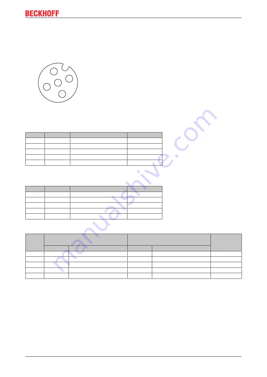
The IO-Link ports are implemented as M12 sockets.

1

2

3

4

5

Fig. 20: M12 socket

EP6224-2022
EP6228-0022

Contact

Function

Description

Core color 

1)

1

L+

Supply voltage (U

S1

)

brown

2

-

-

white

3

L-

GND

blue

4

C/Q

IO-Link data cable

black

5

-

-

grey

EP6224-3022
EP6228-3032

Contact

Function

Description

Core color 

1)

1

L+

Sensor/logic supply (U

S1

)

brown

2

P24

Actuator supply (U

P1

)

white

3

L-

GND to L+

blue

4

C/Q

IO-Link data cable

black

5

N24

GND to P24

grey

EP6228-3132

Contact

X01, X02, X05, X06:

Class A ports

X03, X04, X07, X08:

Class B ports

Core color 

1)

Function

Description

Function

Description

1

L+

Supply voltage (U

S1

)

L+

Sensor/logic supply (U

S1

)

brown

2

DI

Digital input

P24

Actuator supply (U

P1

)

white

3

L-

GND

L-

GND to L+

blue

4

C/Q

IO-Link data cable

C/Q

IO-Link data cable

black

5

-

-

N24

GND to P24

grey

1) 

The core colors apply to M12 sensor cables from Beckhoff:

• ZK2000-5xxx

• ZK2000-6xxx

• ZK2000-7xxx.

Summary of Contents for EP6224

Page 1: ...Documentation EP6224 and EP6228 IO Link Master with protection class IP67 1 5 2019 10 28 Version Date ...

Page 2: ......

Page 3: ...nsions 22 4 1 2 Mounting 25 4 1 3 Tightening torques for plug connectors 25 4 2 Connection 26 4 2 1 Supply voltage 27 4 2 2 EtherCAT 31 4 2 3 IO Link 33 4 3 UL Requirements 35 5 Commissioning and configuration 36 5 1 Configuration in TwinCAT 36 5 2 IO Link configuration 37 5 2 1 Opening the configuration tool 37 5 2 2 Assigning devices to ports 38 5 2 3 Supplementing the device catalog 38 5 2 4 Pa...

Page 4: ...nosis 49 6 1 IO Link Events 49 6 2 ADS Error Codes 50 7 Appendix 52 7 1 General operating conditions 52 7 2 EtherCAT Box EtherCAT P Box Accessories 53 7 3 General note on the introduction of the Beckhoff Identification Code BIC 54 7 4 Support and Service 56 ...

Page 5: ...ification of products that have already been supplied may be made on the basis of the data diagrams and descriptions in this documentation Trademarks Beckhoff TwinCAT EtherCAT EtherCAT G EtherCAT G10 EtherCAT P Safety over EtherCAT TwinSAFE XFC XTS and XPlanar are registered trademarks of and licensed by Beckhoff Automation GmbH Other designations used in this publication may be trademarks whose u...

Page 6: ...for trained specialists in control automation and drive engineering who are familiar with the applicable national standards Description of instructions In this documentation the following instructions are used These instructions must be read carefully and followed without fail DANGER Serious risk of injury Failure to follow this safety instruction directly endangers the life and health of persons ...

Page 7: ... x0x2 Technical Data updated EP6228 x0x2 Introduction updated EP622x Module overview updated Conductor losses 7 8 added Configuration with TwinCAT explanation of tab and IO Link Master updated 1 2 3 Object description and parameterization updated IO Link principles updated 1 2 2 Object description and parameterization updated 1 2 1 Nut torques for connectors updated 1 2 0 EP6228 0022 added Object ...

Page 8: ... can always be replaced with new ones The firmware and hardware version delivery state can be found in the batch number D number printed on the side of the EtherCAT Box Syntax of the batch number D number D WW YY FF HH WW week of production calendar week YY year of production FF firmware version HH hardware version Example with D No 29 10 02 01 29 week of production 29 10 year of production 2010 0...

Page 9: ...eam connection This enables the cabling of EtherCAT Box modules in a line structure Power EtherCAT Fig 1 EtherCAT Box modules Example of cabling in a line structure 2 2 Module overview Module IO Link ports Output current Sensor logic supply L Actuator supply class B ports P24 per port Sum per port Sum EP6224 2022 10 4 x Class A 1 4 A 4 0 A EP6224 3022 10 4 x Class B 1 4 A 4 0 A 2 0 A 2 0 A EP6228 ...

Page 10: ...to point connection is used between the terminal and the device The terminal is parameterised via the EtherCAT master IO Link is designed as an intelligent link between the fieldbus level and the sensor wherein parameterisation information can be exchanged bidirectionally via the IO Link connection The parameterisation of the IO Link devices with service data can be done from TwinCAT via ADS or ve...

Page 11: ... 1 5 In the standard setting the EP6224 functions as a 4 channel input terminal 24 V DC which communicates with connected IO Link devices parameterises them and if necessary changes their operating mode Quick Links Installation 22 Commissioning 36 ...

Page 12: ...M12 socket Cable length max 20 m Specification IO Link V1 1 Transmission rate COM1 4 8 kbit s COM2 38 4 kbit s COM3 230 4 kbit s Sensor logic supply L 24 VDC from the control voltage US max 1 4 A per port max 4 0 A in total Actuator supply P24 Ports class B 24 VDC from peripheral voltage UP max 2 0 A per port max 4 0 A in total Environmental conditions Ambient temperature during operation 25 60 C ...

Page 13: ...following components are included in the scope of delivery 1x EtherCAT Box EP6224 1x protective cap for supply voltage input M8 transparent pre assembled 1x protective cap for supply voltage output M8 black pre assembled 2x protective cap for EtherCAT socket M8 green pre assembled 10x labels blank 1 strip of 10 Pre assembled protective caps do not ensure IP67 protection Protective caps are pre ass...

Page 14: ...riable Process data of the IO Link de vice 1 Module 2 DeviceState Inputs State Ch1 Module 3 1 2 Module 2 DeviceState Inputs State Ch2 Module 4 1 3 Module 2 DeviceState Inputs State Ch3 Module 5 1 4 Module 2 DeviceState Inputs State Ch4 Module 6 1 1 The modules Module 3 to Module 6 only exist in the process data if the corresponding IO Link ports have been configured 37 ...

Page 15: ...Product overview EP6224 and EP6228 15 Version 1 5 2 4 EP6228 2 4 1 Introduction Fig 4 EP6228 0022 Fig 5 EP6228 3032 ...

Page 16: ...ed as an intelligent link between the fieldbus level and the sensor wherein parameterisation information can be exchanged bidirectionally via the IO Link connection The parameterisation of the IO Link devices with service data can be done from TwinCAT via ADS or very conveniently via the integrated IO Link configuration tool In the standard setting the EP6228 functions as a 8 channel input termina...

Page 17: ...ication IO Link V1 1 Transmission rate COM1 4 8 kbit s COM2 38 4 kbit s COM3 230 4 kbit s Sensor logic supply L 24 VDC from the control voltage US max 1 4 A per port max 4 0 A in total 24 VDC from the control voltage US max 4 0 A per port max 16 0 A in total Actuator supply P24 Ports class B 24 VDC from peripheral voltage UP max 4 0 A per port pair 2 max 16 0 A in total Environmental conditions Am...

Page 18: ...ransparent pre assembled 1x protective cap for supply voltage output M8 black pre assembled 2x protective cap for EtherCAT socket M8 green pre assembled 10x labels blank 1 strip of 10 EP6228 3x32 Make sure that the following components are included in the scope of delivery 1x EP6228 3x32 EtherCAT Box 1x Protective cap for supply voltage output 7 8 black pre fitted 2x protective cap for EtherCAT so...

Page 19: ...2 DeviceState Inputs State Ch2 Module 4 1 3 Module 2 DeviceState Inputs State Ch3 Module 5 1 4 Module 2 DeviceState Inputs State Ch4 Module 6 1 5 Module 2 DeviceState Inputs State Ch5 Module 7 1 6 Module 2 DeviceState Inputs State Ch6 Module 8 1 7 Module 2 DeviceState Inputs State Ch7 Module 9 1 8 Module 2 DeviceState Inputs State Ch8 Module 10 1 1 The modules Module 3 to Module 10 only exist in t...

Page 20: ...IO Link ports are defined in the IO Link specification Class A ports Class A ports are intended for the connection of IO Link devices of the type sensor Contacts of a class A port Supply voltage for the IO Link device L L Data cable for serial communication or switching signals C Q Data cable for switching signals optional DI DQ Class B ports Class B ports are intended for the connection of IO Lin...

Page 21: ...he Data storage function It can save a non volatile copy of the parameters of connected devices If a device fails its parameters remain in the memory of the IO Link Master If a defective device is replaced by a new identical device the master can automatically parameterize the new device with the stored parameters ...

Page 22: ...n millimeters Housing features Housing material PA6 polyamide Sealing compound polyurethane Mounting two fastening holes Ø 4 5 mm for M4 Metal parts brass nickel plated Contacts CuZn gold plated Power feed through max 4 A Mounting position variable Protection class IP65 IP66 IP67 conforms to EN 60529 when screwed together Dimensions H x W x D approx 126 x 60 x 26 5 mm without connectors ...

Page 23: ...ures Housing material PA6 polyamide Sealing compound polyurethane Mounting two fastening holes Ø 4 5 mm for M4 Metal parts brass nickel plated Contacts CuZn gold plated Power feed through max 4 A Mounting position variable Protection class IP65 IP66 IP67 conforms to EN 60529 when screwed together Dimensions H x W x D approx 126 x 60 x 26 5 mm without connectors ...

Page 24: ...PA6 polyamide Sealing compound polyurethane Mounting two fastening holes Ø 4 5 mm for M4 Metal parts brass nickel plated Contacts CuZn gold plated Power feed through max 16 A at 40 C according to IEC 60512 3 Mounting position variable Protection class IP65 IP66 IP67 conforms to EN 60529 when screwed together Dimensions H x W x D approx 150 x 60 x 26 5 mm without connectors ...

Page 25: ... guaranteed if all cables and connectors are connected Protect the plug connectors against dirt during the assembly Mount the module with two M4 screws in the centrally located fastening holes 4 1 3 Tightening torques for plug connectors Screw connectors tight with a torque wrench e g ZB8801 from Beckhoff Connector diameter Tightening torque M8 0 4 Nm M12 0 6 Nm 7 8 1 5 Nm ...

Page 26: ...ount connectors with the specified torque 25 Use a torque wrench e g Beckhoff ZB8801 Seal unused connectors with protective caps Ensure the correct seating of pre assembled protective caps Protective caps are pre assembled at the factory to protect connectors during transport They may not be tight enough to ensure IP67 protection ...

Page 27: ...r EtherCAT Observe the color coding of the connectors in order to avoid incorrect insertion black Supply voltage green EtherCAT Two connectors at the low end of the modules are used for feeding and routing the supply voltages Power supply IN plug left Downstream connection OUT socket right Fig 11 Connector for the supply voltages Connection Plug Feed in Socket Forwarding 3 1 2 4 3 1 2 4 Fig 12 M8 ...

Page 28: ... into account the voltage drop on the supply line when planning a system Avoid the voltage drop being so high that the supply voltage at the box lies below the minimum nominal voltage Variations in the voltage of the power supply unit must also be taken into account Voltage drop on the supply line Vert Faktor 0 45 cm V 5 10 15 20 2 4 6 8 10 25 0 0 12 30 Vert Faktor 0 45 cm V Voltage drop V Cable l...

Page 29: ...ply IN plug left Downstream connection OUT socket right Fig 14 Connector for the supply voltages Connection 1 2 3 4 5 5 4 3 2 1 Plug Feed in Socket Forwarding Fig 15 7 8 plug connectors Contact Function Description Core color 1 1 GNDP GND to UP Black 2 GNDS GND to US Blue 3 FE Functional earth Grey 4 US Control voltage Brown 5 UP Peripheral voltage White 1 The core colors apply to cables of the ty...

Page 30: ...t 4 2 1 2 3 Conductor losses Take into account the voltage drop on the supply line when planning a system Avoid the voltage drop being so high that the supply voltage at the box lies below the minimum nominal voltage Variations in the voltage of the power supply unit must also be taken into account Voltage drop on the supply line 5 10 15 20 0 4 0 8 1 2 1 6 25 0 0 2 0 30 Vert Faktor 2 75 cm V Volta...

Page 31: ...32 ZK1090 3xxx xxxx TIA 568B Tx 1 yellow1 orange white white orange Tx 4 orange1 orange orange Rx 2 white1 blue white white green Rx 3 blue1 blue green Shield Housing Shield Shield Shield 1 Core colors according to EN 61918 Adaptation of core colors for cables ZB9030 ZB9032 and ZK1090 3xxxx xxxx For standardization the core colors of the ZB9030 ZB9032 and ZK1090 3xxx xxxx cables have been changed ...

Page 32: ... the status of the slave in the EtherCAT network LED Meaning off Slave is in Init state flashes uniformly Slave is in Pre Operational state flashes sporadically Slave is in Safe Operational state lit Slave is in Operational state Description of the EtherCAT slave states 4 2 2 3 Cables For connecting EtherCAT devices only shielded Ethernet cables that meet the requirements of at least category 5 CA...

Page 33: ...olor 1 1 L Sensor logic supply US1 brown 2 P24 Actuator supply UP1 white 3 L GND to L blue 4 C Q IO Link data cable black 5 N24 GND to P24 grey EP6228 3132 Contact X01 X02 X05 X06 Class A ports X03 X04 X07 X08 Class B ports Core color 1 Function Description Function Description 1 L Supply voltage US1 L Sensor logic supply US1 brown 2 DI Digital input P24 Actuator supply UP1 white 3 L GND L GND to ...

Page 34: ...ed illuminated flashes sporadically green Possibilities IO Link connection attempt No IO Link device connected Incorrect IO Link device connected IO Link device defective flashing green IO Link communication active green illuminated Logic level high 1 1 Port configured as digital input or output 2 Digital input DI EP6228 3132 only The LED lights up when a high level is present on the digital input...

Page 35: ...mum 4 Amp or by a 24 VDC power source that has to satisfy NEC class 2 A NEC class 2 power supply shall not be connected in series or parallel with another class 2 power source CAUTION CAUTION To meet the UL requirements the EtherCAT Box Modules must not be connected to unlimited power sources Networks CAUTION CAUTION To meet the UL requirements EtherCAT Box Modules must not be connected to telecom...

Page 36: ...n in TwinCAT An EtherCAT Box must be configured in TwinCAT so that its functions can be used in a PLC program The following link will take you to a quick start guide describing the configuration of an EtherCAT Box in TwinCAT https infosys beckhoff com content 1033 epioconfiguration index html id 6991403443235907429 ...

Page 37: ...onfiguration tool opens Overview The configuration tool contains two fields Ports The left hand field Ports shows a list of the ports of the IO Link master If a device has been assigned to a port the device designation is shown next to the port Catalog The right hand field Catalog shows the device catalog The device catalog contains a list of the IO Link devices for which a device description exis...

Page 38: ...The IO Link master requests all connected devices to identify themselves Each detected device is automatically assigned to the port to which it is connected Entering the device description manually 1 Right click on a port 2 Click on Create Device in the context menu ð A dialog box opens 3 Enter the items of information that describe the IO Link device 5 2 3 Supplementing the device catalog Followi...

Page 39: ...Device Katalog übernommen Store Store the current parameter values in the Parameter Server Data Storage 21 5 2 6 Configuring a port as a digital input output IO Link ports can also be configured as digital inputs or digital outputs This allows digital sensors and actuators having no IO Link functionality to be connected to IO Link ports 1 Expand the Std I O tree node in the Catalog field ð The ope...

Page 40: ...n between online offline dictionary existence of current XML description use CoE reload for resetting changes Introduction The CoE overview contains objects for different intended applications Objects required for parameterization during commissioning Objects intended for regular operation e g through ADS access Objects for indicating internal settings may be fixed Profile specific objects for exp...

Page 41: ...ionalities of the IO link device e g SPDU supported Bit 0 SPDU Bit 1 Type1 Bit 7 PHY1 UINT8 RW 0x00 0dez 80n0 22 Min cycle time The cycle time refers to the communication between the IO link master and the IO link device This value is transferred in the IO link format for Min Cycle Time Bit 6 und 7 Time Base Bit 0 to 5 Multiplier 0x00 The IO Link master automatically uses the small est possible up...

Page 42: ...ComStop none cyclic communication data are exchanged on demand UINT16 RW 0x0000 0dez 5 3 2 Objects for regular operation In normal functional range the EL6224 has no such objects Complete overview 5 3 3 Standard objects 0x1000 0x1FFF The standard objects of all EtherCAT slaves have the same meaning Index 1000 Device type Index hex Name Meaning Data type Flags Default 1000 0 Device type Device Type...

Page 43: ...oad of the Backup Entries UINT8 RO 0x01 1dez 10F0 01 Checksum Checksum over all backup entries UINT32 RO 0x00000000 0dez Index 1600 IO RxPDOPDO Map Ch 1 Index hex Name Meaning Data type Flags Default 1600 0 IO RxPDOPDO Map Ch 1 PDO Mapping RxPDO 1 UINT8 RW 0x01 1dez 1600 01 SubIndex 001 1 PDO Mapping entry 8 bits align UINT32 RW 0x0000 00 8 Index 1601 IO RxPDOPDO Map Ch 2 Index hex Name Meaning Da...

Page 44: ...3 3 PDO Mapping entry object 0xF100 Diagnosis Sta tus data entry 0x03 State Ch3 UINT32 RW 0xF100 03 8 1A04 04 SubIndex 004 4 PDO Mapping entry object 0xF100 Diagnosis Sta tus data entry 0x04 State Ch4 UINT32 RW 0xF100 04 8 Index 1C00Sync manager type Index hex Name Meaning Data type Flags Default 1C00 0 Sync manager type Usage of the Sync Manager channels UINT8 RO 0x04 4dez 1C00 01 SubIndex 001 Sy...

Page 45: ... Cycle time UINT32 RW 0x000186A0 100000dez 1C32 03 Shift time Time between SYNC0 Event and Outputs Valid in ns only in DC Mode UINT32 RO 0x00000000 0dez 1C32 04 Sync modes supported Supported synchronization modes Bit 0 1 Free Run is supported Bit 1 1 Synchron with SM 2 Event is supported Bit 2 3 01 DC Mode is supported Bit 4 5 10 Output Shift with SYNC1 Event only DC Mode Bit 14 1 dynamic times c...

Page 46: ...0xC007 49159dez 1C33 05 Minimum cycle time same as 1C32 05 UINT32 RO 0x000186A0 100000dez 1C33 06 Calc and copy time time between Input Latch and the availability of the in puts for the master in ns only in DC Mode UINT32 RO 0x00000000 0dez 1C33 08 Command same as 1C32 08 UINT16 RW 0x0000 0dez 1C33 09 Delay time time between SYNC1 Event and Input Latch in ns only in DC Mode UINT32 RO 0x00000000 0d...

Page 47: ...master and the IO link device This value is transferred in the IO link format for Min Cycle Time Bit 6 und 7 Time Base Bit 0 to 5 Multiplier UINT8 RO 0x00 0dez 90n0 22 Offset time reserved UINT8 RO 0x00 0dez 90n0 23 Process data in length These parameters are transferred in the IO link format for Process data in length Bit 7 BYTE indicates whether the value in LENGTH interpreted as bit length bit ...

Page 48: ...e objects of two chan nels UINT16 RO 0x0010 16dez F000 02 Maximum number of mod ules Number of channels UINT16 RO 0x0004 4dez Index F008 Code word Index hex Name Meaning Data type Flags Default F008 0 Code word reserved UINT32 RW 0x00000000 0dez Index F010 Module list Index hex Name Meaning Data type Flags Default F010 0 Module list Max Subindex UINT8 RW 0x04 4dez F010 01 SubIndex 001 UINT32 RW 0x...

Page 49: ...ages can be taken from the vendor documentation The IO Link device can be directly allocated on the basis of the port number The events occurring can be managed using the various buttons Update History if the Auto Update field is not selected then the current events can be displayed via the Update History button Auto Update if this field is selected then the list of events occurring is automatical...

Page 50: ...LE SHOT DL 56 Calculated PDU checksum in master does not match actual received SPDU PDU checksum error device remote S_PDU_CHECK ERROR SiNGLE SHOT DL 56 Calculated PDU checksum in device does not match actual received SPDU PDU flow control error remote S_PDU_FLOW ERROR SiNGLE SHOT DL 56 Violation of flow control rule during transfer of SPDU be tween master and device Illegal PDU service primitive ...

Page 51: ...fferent protocol revision Access denied 23 Negative service response initiated by a communication error eg IO Link connection interrupted Parameter value out of range 30 Service PDU transferred but not processed due to device error See error details in Additional Code Parameter value above limit 31 Service PDU transferred but not processed due to device error See error details in Additional Code P...

Page 52: ...ater protection Definition 0 Non protected 1 Protected against water drops 2 Protected against water drops when enclosure tilted up to 15 3 Protected against spraying water Water sprayed at an angle up to 60 on either side of the ver tical shall have no harmful effects 4 Protected against splashing water Water splashed against the disclosure from any direction shall have no harmful effects 5 Prote...

Page 53: ...king labels on request Tools Ordering information Description ZB8800 torque wrench for M8 cables with knurl incl ratchet ZB8800 0001 M12 ratchet for torque wrench ZB8800 ZB8800 0002 M8 ratchet field assembly for torque wrench ZB8800 ZB8801 0000 torque wrench for hexagonal plugs adjustable ZB8801 0001 torque cable key M8 wrench size 9 for torque wrench ZB8801 0000 ZB8801 0002 torque cable key M12 w...

Page 54: ...r internal handling and administration of the products When scanning the BICs you will find the following information Coded information on the BIC Item no Type of information Explanation 1 Beckhoff order number Beckhoff order number 2 Beckhoff Traceability Number BTN Unique serial number see note below 3 Article description Beckhoff article description e g EL1008 4 Quantity Quantity in packaging u...

Page 55: ...ber 52S 23 52S2304853 1 004 Structure of the BIC Example of an item of information made up of positions 1 4 and 6 The data identifiers are each marked in red for clearer illustration 1P072222SBTNk4p562d71KEL1809 Q1 51S678294104 1P S 1K Q 51S Order number BTN Article description ID Quantity BTN An important component of the BIC is the Beckhoff Traceability Number BTN item no 2 The BTN is a unique 8...

Page 56: ...ckhoff components there Beckhoff Headquarters Beckhoff Automation GmbH Co KG Huelshorstweg 20 33415 Verl Germany Phone 49 5246 963 0 Fax 49 5246 963 198 e mail info beckhoff com Beckhoff Support Support offers you comprehensive technical assistance helping you not only with the application of individual Beckhoff products but also with other wide ranging services support design programming and comm...

Page 57: ...Dimensions 22 Fig 9 Dimensions 23 Fig 10 Dimensions 24 Fig 11 Connector for the supply voltages 27 Fig 12 M8 connector 27 Fig 13 Status LEDs for the supply voltages 28 Fig 14 Connector for the supply voltages 29 Fig 15 7 8 plug connectors 29 Fig 16 Status LEDs for the supply voltages 30 Fig 17 EtherCAT connector 31 Fig 18 M8 socket 31 Fig 19 EtherCAT Status LEDs 32 Fig 20 M12 socket 33 Fig 21 Stat...

Reviews: