background image

Application samples

EL6601, EL6614

122

Version: 4.2

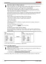
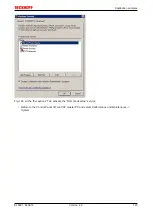
Fig. 147: Choose security settings for Windows Firewall

• If the Windows firewall is activated click on tab 

Exceptions

• Select 

Remote Desktop

 and confirm with 

OK

Summary of Contents for EL6601

Page 1: ...Documentation EL6601 EL6614 Switch Terminals for Ethernet 4 2 2019 05 03 Version Date...

Page 2: ......

Page 3: ...on 33 3 1 EtherCAT basics 33 3 2 EtherCAT cabling wire bound 33 3 3 General notes for setting the watchdog 34 3 4 EtherCAT State Machine 36 3 5 CoE Interface 38 3 6 Distributed Clock 43 4 Mounting and...

Page 4: ...printer 114 6 3 Application sample Service interface with remote desktop 119 6 4 Application sample Lower level control system 129 6 5 Application sample setting up an EtherCAT Master PC as a network...

Page 5: ...ata diagrams and descriptions in this documentation Trademarks Beckhoff TwinCAT EtherCAT EtherCAT P Safety over EtherCAT TwinSAFE XFC and XTS are registered trademarks of and licensed by Beckhoff Auto...

Page 6: ...trained specialists in control automation and drive engineering who are familiar with the applicable national standards Description of instructions In this documentation the following instructions ar...

Page 7: ...data section updated Update chapter Mounting and wiring 3 0 Notes on cable redundancy added 2 9 Notes Subscriber filter diagnostic data added 2 8 Technical notes added 2 7 Technical notes added 2 6 T...

Page 8: ...by Beckhoff In principle a device with a higher revision can replace a device with a lower revision unless specified otherwise e g in the documentation Associated and synonymous with each revision the...

Page 9: ...u hardware version of the I O PCB Example D 22081501 calendar week 22 of the year 2008 firmware version of bus PCB 1 hardware version of bus PCB 5 firmware version of I O PCB 0 no firmware necessary f...

Page 10: ...4 10 Version 4 2 Fig 2 EK1100 EtherCAT coupler standard IP20 IO device with serial batch number Fig 3 CU2016 switch with serial batch number Fig 4 EL3202 0020 with serial batch number 26131006 and uni...

Page 11: ...mber 158102 Fig 6 EP1908 0002 IP67 EtherCAT Safety Box with batch number date code 071201FF and unique serial number 00346070 Fig 7 EL2904 IP20 safety terminal with batch number date code 50110302 and...

Page 12: ...The 4 port Ethernet switch terminal EL6614 purposefully forwards the incoming frames from the ports to the destination ports In full duplex mode it thus enables collision free communication of the co...

Page 13: ...unction for firmware updates 146 of the terminal flashing State of the EtherCAT State Machine PREOP function for mailbox communication and different standard settings set single flash State of the Eth...

Page 14: ...ambient temperature range during operation 25 C 60 C extended temperature range Horizontal installation position 25 C 60 C extended temperature range all other installation positions 25 C 45 C see no...

Page 15: ...EL66xx is configured in the PDO settings of the EL66xx when EtherCAT starts up and cannot be changed online Non real time data exchange In parallel with this the EL66xx can transfer Ethernet frames th...

Page 16: ...an overrun causes data to be lost higher protocol layers in an Ethernet network are responsible for repeating the transmission Overruns The following measures can be used to counter overruns activatin...

Page 17: ...erCAT fieldbus The EoE method Ethernet over EtherCAT is used for the EL66xx Dedicated settings are available for this in the System Manager Data throughput The data throughput of the EL66xx in Etherne...

Page 18: ...on boundary conditions Address assignment From FW03 onwards the EL6601 6614 can also assign IP addresses to connected devices and works as a DHCP or BOOTP server for one device The following settings...

Page 19: ...se communicated to the client the device Only one address can be assigned i e no switch with connected subscribers may follow the address range must be identical to that of the EtherCAT adapter DHCP S...

Page 20: ...ries for SyncManager 0 and 1 To increase the data throughput the size of the mailbox can be increased to 1024 Byte see Fig Increasing the Size of the Mailbox Default mailbox size As of Revision EL66xx...

Page 21: ...frames that are larger than the EL6601 mailbox are fragmented by the EL6601 or the EtherCAT master and reassembled after passing through the EtherCAT system Virtual switch setting The EL66xx devices...

Page 22: ...esigned with a previous EL6601 version EL6601 0000 0000 this can be re placed with versions from EL6601 0000 0017 without problem If the system was designed for ver sion EL6601 0000 0017 or higher rep...

Page 23: ...publishers subscribers configured in the EL66xx real time cycle times down to 500 s or below are possible Typical throughput values for EL6601 FW08 Rev EL6601 0000 0018 are 1 publisher with 1000 byte...

Page 24: ...ode 3072 bytes If more publisher or subscriber data are required for an application the SyncManagers can be modified accordingly The mailbox cannot be modified 2 5 2 Settings in the System Manager App...

Page 25: ...Stack 22 should be deactivated A maximum of 32 for each publishers and subscriber are permitted per EL66xx 2 5 4 Suppress publisher Applicable TwinCAT from version 2 11 EL6601 from FW08 EL6614 from FW...

Page 26: ...ain the AmsNetId and Variables ID to be checked The EL66xx devices can therefore filter according to the incoming publisher IDs and compare them with their own subscriber IDs For this purpose the publ...

Page 27: ...Append device In the selection dialog an EL6601 is offered as a real time Ethernet device The EL6601 must also be selected here when an EL6614 is being used Fig 24 Select EL6601 An imaginary box is n...

Page 28: ...25 Append box Fig 26 Append network variable The EL6601 device is now linked to the actual EL6601 or EL6614 in the selection dialog Adapter tab Search Fig 27 Link device with EL6601 All further steps...

Page 29: ...figure an EL66xx as a transmitter receiver of network variables Fig 28 Append new device Select the EtherCAT Automation Protocol in the device dialog Fig 29 Select EtherCAT Automation Protocol The new...

Page 30: ...further steps are done as described in the preceding sections 2 6 Configuration in the CX20x0 CX50x0 system The embedded PCs of CX20x0 and CX50x0 series feature a special integrated I O interface for...

Page 31: ...mes visible when the configuration is activated To configure the Ethernet port offline proceed as follows Due to the automatic E bus and K bus switching any terminal should be connected with the appro...

Page 32: ...ings are applied and saved Even if the port disappears again the settings are retained for subsequent commissioning If the problem persists i e if the Ethernet port of the EL66xx still fails to show u...

Page 33: ...C 8802 3 Pin Color of conductor Signal Description 1 yellow TD Transmission Data 2 orange TD Transmission Data 3 white RD Receiver Data 6 blue RD Receiver Data Due to automatic cable detection auto cr...

Page 34: ...minal for longer than the set and activated SM watchdog time e g in the event of a line interruption the watchdog is triggered and the outputs are set to FALSE The OP state of the terminal is unaffect...

Page 35: ...If the checkbox is not activated nothing is downloaded and the ESC settings remain unchanged Multiplier Multiplier Both watchdogs receive their pulses from the local terminal cycle divided by the wat...

Page 36: ...r switching off of the SM watchdog via SM watchdog 0 is only implemented in terminals from version 0016 In previous versions this operating mode should not be used CAUTION Damage of devices and undefi...

Page 37: ...perational Safe Op During transition between Pre Op and Safe Op the EtherCAT slave checks whether the sync manager channels for process data communication and if required the distributed clocks settin...

Page 38: ...libration values for analog measurement or passwords The order is specified in 2 levels via hexadecimal numbering main index followed by subindex The value ranges are Index 0x0000 0xFFFF 0 65535dez Su...

Page 39: ...ameters are still available after a restart The situation may be different with other manufacturers An EEPROM is subject to a limited lifetime with respect to write operations From typically 100 000 w...

Page 40: ...ue is to be stored permanently enter it in the Startup list The order of the Startup entries is usually irrelevant Fig 42 Startup list in the TwinCAT System Manager The Startup list may already contai...

Page 41: ...ine The actual current slave list is read This may take several seconds depending on the size and cycle time The actual identity is displayed The firmware and hardware version of the equipment accordi...

Page 42: ...the placeholder n tends to be used for the individual channel numbers In the CoE system 16 indices each with 255 subindices are generally sufficient for representing all channel parameters The channel...

Page 43: ...nit 1 ns Zero point 1 1 2000 00 00 Size 64 bit sufficient for the next 584 years however some EtherCAT slaves only offer 32 bit support i e the variable overflows after approx 4 2 seconds The EtherCAT...

Page 44: ...als with front unlocking The terminal modules are fastened to the assembly surface with the aid of a 35 mm mounting rail e g mounting rail TH 35 15 Fixing of mounting rails The locking mechanism of th...

Page 45: ...ace Avoid canting of the module you should stabilize the module with the other hand if required 4 3 Positioning of passive Terminals Hint for positioning of passive terminals in the bus terminal block...

Page 46: ...ave been specified When installing high power dissi pation terminals ensure that an adequate spacing is maintained between other components above and be low the terminal in order to guarantee adequate...

Page 47: ...own in Fig Recommended distances for standard installation position is recommended Other installation positions All other installation positions are characterized by different spatial arrangement of t...

Page 48: ...ure range ET in potentially explosive areas Measures must be taken to protect against the rated operating voltage being exceeded by more than 40 due to short term interference voltages The individual...

Page 49: ...60 C 4 6 ATEX Documentation Notes about operation of the Beckhoff terminal systems in potentially explosive ar eas ATEX Pay also attention to the continuative documentation Notes about operation of th...

Page 50: ...eXtended Automation Visual Studio Integration Choice of the programming language Supports object orientated extension of IEC 61131 3 Usage of C C as programming language for real time applications Con...

Page 51: ...aces listed under Compatible devices can be assigned a driver via the Install button A driver should only be installed on compatible devices A Windows warning regarding the unsigned driver can be igno...

Page 52: ...ties of the EtherCAT device can be opened by double click on Device EtherCAT within the Solution Explorer under I O After the installation the driver appears activated in the Windows overview for the...

Page 53: ...Commissioning EL6601 EL6614 53 Version 4 2 Fig 54 Exemplary correct driver setting for the Ethernet port Other possible settings have to be avoided...

Page 54: ...Commissioning EL6601 EL6614 54 Version 4 2 Fig 55 Incorrect driver settings for the Ethernet port...

Page 55: ...s where an EL6601 or similar devices are used it is useful to specify a fixed IP address for this port via the Internet Protocol TCP IP driver setting and to disable DHCP In this way the delay associa...

Page 56: ...that was current at the time when the TwinCAT build was created For TwinCAT 2 11 TwinCAT 3 and higher the ESI directory can be updated from the System Manager if the programming PC is connected to the...

Page 57: ...ision 1019 or for an older revision The ESI must then be requested from the manufacturer in this case Beckhoff b an ESI is present for the EL2521 0000 device but only in an older revision e g 1018 or...

Page 58: ...deleted as follows close all System Manager windows restart TwinCAT in Config mode delete OnlineDescription0000 xml restart TwinCAT System Manager This file should not be visible after this procedure...

Page 59: ...1 EL6614 59 Version 4 2 Reasons may include Structure of the xml does not correspond to the associated xsd file check your schematics Contents cannot be translated into a device description contact th...

Page 60: ...s For the present publisher subscriber service in combination with an EL6601 EL6614 terminal select EtherCAT Automation Protocol via EL6601 Fig 64 Selecting the EtherCAT connection TwinCAT 2 11 TwinCA...

Page 61: ...TwinCAT 3 The dialog for selecting a new device opens Only devices for which ESI files are available are displayed Only devices are offered for selection that can be appended to the previously select...

Page 62: ...Information Fig 69 Display of device revision In many cases several device revisions were created for historic or functional reasons e g through technological advancement For simplification purposes s...

Page 63: ...on This also enables subsequent replacement of devices without changing the configuration different specifications are possible for drives Example If an EL2521 0025 1018 is specified in the configurat...

Page 64: ...Commissioning EL6601 EL6614 64 Version 4 2 Fig 72 EtherCAT terminal in the TwinCAT tree left TwinCAT 2 right TwinCAT 3...

Page 65: ...The online search is not available in RUN mode production operation Note the differentiation be tween TwinCAT programming system and TwinCAT target system The TwinCAT 2 icon or TwinCAT 3 icon within t...

Page 66: ...e The respective devices are lo cated in the stored ESI data and integrated in the configuration tree in the default state defined there Fig 77 Example default state NOTE Slave scanning in practice in...

Page 67: ...configuration B tsm in order to check the built machine However if the series machine production department now doesn t use B tsm but instead carries out a scan to create the productive configuration...

Page 68: ...witched to online state OPERATIONAL Fig 83 Config FreeRun query left TwinCAT 2 right TwinCAT 3 In Config FreeRun mode the System Manager display alternates between blue and red and the EtherCAT device...

Page 69: ...evice is detected i e an EtherCAT slave for which no ESI XML description is available In this case the System Manager offers to read any ESI that may be stored in the device This case is described in...

Page 70: ...nfiguration is then replaced by the revision found this can affect the supported process data and functions If a scan is initiated for an existing configuration the actual I O environment may match th...

Page 71: ...based on the higher revision number Device selection based on revision compatibility The ESI description also defines the process image the communication type between master and slave device and the...

Page 72: ...nCAT offers a function Change to Compatible Type for the exchange of a device whilst retaining the links in the task Fig 92 Dialog Change to Compatible Type left TwinCAT 2 right TwinCAT 3 This functio...

Page 73: ...tabs are now available for configuring the terminal And yet the dimension of complexity of a subscriber determines which tabs are provided Thus as illustrated in the example above the terminal EL3751...

Page 74: ...ing the start up phase Tick the control box to the left of the input field in order to modify the default value Previous Port Name and port of the EtherCAT device to which this device is connected If...

Page 75: ...modifications include mask out a channel displaying additional cyclic information 16 bit display instead of 8 bit data size etc In so called intelligent EtherCAT devices the process data information...

Page 76: ...of incorrect configuration the EtherCAT slave usu ally refuses to start and change to OP state The System Manager displays an invalid SM cfg log ger message This error message invalid SM IN cfg or inv...

Page 77: ...sent to the mailbox Move Up This button moves the selected request up by one position in the list Move Down This button moves the selected request down by one position in the list New This button add...

Page 78: ...object can be read but no data can be written to the object read only P An additional P identifies the object as a process data object Value Value of the object Update List The Update list button upda...

Page 79: ...bjects included in the object list of the slave is uploaded from the slave via SDO information The list below can be used to specify which object types are to be uploaded Offline via EDS File If this...

Page 80: ...again Current State Indicates the current state of the EtherCAT device Requested State Indicates the state requested for the EtherCAT device DLL Status Indicates the DLL status data link layer status...

Page 81: ...ist is deactivated not selected and greyed out this indicates that the input is excluded from the PDO assignment In order to be able to select a greyed out PDO the currently selected PDO has to be des...

Page 82: ...y briefly deals with a number of aspects of EtherCAT Slave operation under TwinCAT More detailed information on this may be found in the corresponding sections of for instance the EtherCAT System Docu...

Page 83: ...he EtherCAT Master updated in every cycle red Output variables from the Slave to the EtherCAT Master updated in every cycle green Information variables for the EtherCAT Master that are updated acyclic...

Page 84: ...ation This may possibly have effects on the process data of other Slaves that are located in the same Syn cUnit In order for the higher level PLC task or cor responding control applications to be able...

Page 85: ...d locally in the slave depends on the device EL terminals except the EL66xx are able to save in this way The user must manage the changes to the StartUp list Commissioning aid in the TwinCAT System Ma...

Page 86: ...ual operation After the operating power is switched on an EtherCAT Slave must go through the following statuses INIT PREOP SAFEOP OP to ensure sound operation The EtherCAT Master directs these statuse...

Page 87: ...set as standard EtherCAT Master OP Slaves OP This setting applies equally to all Slaves Fig 108 Default behaviour of the System Manager In addition the target state of any particular Slave can be set...

Page 88: ...lave Fig 110 PLC function blocks Note regarding E Bus current EL ES terminals are placed on the DIN rail at a coupler on the terminal strand A Bus Coupler can supply the EL terminals added to it with...

Page 89: ...above a warning message E Bus Power of Terminal is output in the logger window when such a configuration is activated Fig 112 Warning message for exceeding E Bus current NOTE Caution Malfunction poss...

Page 90: ...issing objects 5 3 1 Objects for commissioning Index 1018 Identity Index hex Name Meaning Data type Flags Default 1018 0 Identity Information for identifying the slave UINT8 RO 0x04 4dec 1018 01 Vendo...

Page 91: ...ile used 5002 UINT32 RO 0x0000138A 5002dec Index 1008 Device name Index hex Name Meaning Data type Flags Default 1008 0 Device name Device name of the EtherCAT slave STRING RO e g EL6601 0000 0017 Ind...

Page 92: ...Channel 1 Mailbox Write UINT8 RO 0x01 1dec 1C00 02 SubIndex 002 Sync Manager Type Channel 2 Mailbox Read UINT8 RO 0x02 2dec 1C00 03 SubIndex 003 Sync Manager Type Channel 3 Outputs UINT8 RO 0x02 2dec...

Page 93: ...de only UINT32 RW 0x00000000 0dec 1C32 04 Sync modes sup ported Supported synchronization modes Bit 1 1 Synchron with SM 2 event is supported UINT16 RW 0x0002 2dec Index 1C33 SM input parameter only w...

Page 94: ...67FA Receiving Frame Identification Ignore Item Net Var Subscriber Index hex Name Meaning Data type Flags Default 6002 n 8 0 Receiving Frame Identification Ignore Item Net Var Subscriber Max subindex...

Page 95: ...n 8 07 Cycle Index Entry is incremented with each Publisher cycle UINT16 RO P 7000 n 8 08 reserved reserved UINT16 RW P 7000 n 8 09 Net Var 001 Id Identification of network variables UINT16 RW P 7000...

Page 96: ...ength of the data Byte 4 5 Quality UINT48 RW P 7003 n 8 0B Net Var 001 Data Data range STRING RW P 7003 n 8 3 y 6 Net Var y Id Identification of network variables UINT16 RW P 7003 n 8 3 y 7 Net Var y...

Page 97: ...t driver for TwinCAT must be installed Publisher Subscriber model In the Publisher Subscriber model the Publisher makes variables available Subscribers can subscribe to a variable The Publisher can ma...

Page 98: ...all PCs 5 4 2 Configuration of the Publisher In the TwinCAT System Manager a new box is added for the Publisher under the RT Ethernet device Insert a Publisher Box A Publisher box must be added under...

Page 99: ...ts of the inserted variables The FrameState input under the box indicates the current status of the sent Ethernet frames The following values are possible for the FrameState Short description Value De...

Page 100: ...r VarState Short description Value Description Not sent variable skipped 0x0001 A Control Word can be written in the VarCtrl output under the network variable The following values are possible for Fra...

Page 101: ...riber under the RT Ethernet device Adding a Subscriber box and linking the network variables A Subscriber box must be added under the RT Ethernet device Fig 118 Creation of an RT Ethernet device Fig 1...

Page 102: ...th right click The link to a Publisher variable can be created automatically First you need to find the Publisher computer All variables of this Publisher are then shown in a list Fig 122 Searching fo...

Page 103: ...riable indicate the current status or control of the received network variable VarState and VarCtrl are reserved and are currently not supported Quality of the network variables The quality of a netwo...

Page 104: ...Version 4 2 Fig 124 Time diagram Online value of the Quality variables In addition to the Quality variables the CycleIndex variable is incremented in each Publisher cycle Fig 125 Time diagram Online v...

Page 105: ...identified as Beckhoff real time Ethernet through the Ethertype 0x88A4 and treated as an RT protocol in the TwinCAT PC In contrast to TCP as a connection less protocol UDP requires no acknowledgement...

Page 106: ...blisher or Subscriber group may only be used once within a TwinCAT device see Fig Sample for communication via network variables Publishers 1 and 2 on PC1 must have different IDs 10 and 8 although the...

Page 107: ...Commissioning EL6601 EL6614 107 Version 4 2 Fig 127 Sample for communication via network variables...

Page 108: ...variables must lie at an address that is divisible by 4 then all 2 byte variables must lie at an address that is divisible by 2 then all 1 byte variables Further recommendations if STRING x is used t...

Page 109: ...r unique MAC address Please refer to the relevant literature for further rules relating to the formation of multicast MAC IP addresses Unicast Either direct entry of the destination MAC or via the AMS...

Page 110: ...simple network devices such as printers to crash With short cycle times all network traffic may become blocked We strongly recommend using unicast addressing taking into account vari able identificat...

Page 111: ...ion number with which the variable is sent Can be changed online via PLC where appropriate Data exchange see above not for EL66xx On change only NWV is only sent if the value changes not for EL66xx Su...

Page 112: ...mits NWVs with a certain ID for this subscriber Can be changed dynamically via PLC where appropriate Ignore Data Type Hash Hash calculation is currently not supported Process data Quality See explanat...

Page 113: ...down to 500 s or below are possible Typical throughput values for EL6601 FW08 Rev EL6601 0000 0018 are 1 publisher with 1000 bytes 1 subscriber with 1000 bytes simultaneous bidirectional operation 2...

Page 114: ...nal SP 2 TwinCAT version 2 10 Build 1305 and INTEL PRO 100 VE Ethernet adapter Beckhoff Ethernet coupler terminal EK1100 terminals EL1012 EL6601 and EL9010 Printer HP LaserJet 4200tn A network printer...

Page 115: ...601 in the configuration Connect the network printer with the EL6601 via a CAT 5 1 1 cable In the Control Panel of the controller IPC check the network adapter via which the EtherCAT system is operate...

Page 116: ...116 Version 4 2 Fig 137 Context Menu LAN Connection TwinCAT LAN Adapter Properties Fig 138 Properties Internet Protocol TCP IP Enter an IP address for the subnet of the network printer e g 192 168 0 1...

Page 117: ...ber range subnet mask of the master PC Configure the network printer in the configuration menu of the printer and allocate the printer an IP address from the IP number range of the subnet defined abov...

Page 118: ...Version 4 2 Fig 141 Select Local Printer radio button Fig 142 Select Connection Type In the following menu under Printer Name or IP Address enter the IP address of the printer defined in the configur...

Page 119: ...e been tested with a test configuration and are described accordingly Certain deviations when setting up actual applications are possible The following hardware was used for the test configuration Twi...

Page 120: ...ace with remote desktop PC Configuration at the TwinCAT master PC Start the TwinCAT System Manager in Config mode read the Bus Terminal configuration and activate free run mode The EL6601 should appea...

Page 121: ...configuration of a network printer the IP number of the EtherCAT network port of the TwinCAT Master PC in the subnet is e g 192 168 0 1 Open the Control Panel of the TwinCAT master PC and click on Se...

Page 122: ...lication samples EL6601 EL6614 122 Version 4 2 Fig 147 Choose security settings for Windows Firewall If the Windows firewall is activated click on tab Exceptions Select Remote Desktop and confirm with...

Page 123: ...cation samples EL6601 EL6614 123 Version 4 2 Fig 148 At the Exceptions Tab activate the Remote desktop service Return to the Control Panel of TwinCAT master PC and select Performance and Maintenance S...

Page 124: ...L6614 124 Version 4 2 Fig 149 Select Service and Maintenance from System in the View Control Panel Click on the Remote tab and in the Remote Desktop category select the option Allow users to establish...

Page 125: ...For a remote desktop connection with the TwinCAT master PC via the EL6601 the network address of the service PC has to be set according to the IP number range of the TwinCAT master PC subnet Connect...

Page 126: ...Application samples EL6601 EL6614 126 Version 4 2 Fig 152 Context Menu Network Environment Properties Fig 153 Context Menu LAN Connection Ethernet LAN Adapter Properties...

Page 127: ...K Fig 155 Entry of the IP address of the subnetwork of the Service PC The Ethernet connection to the TwinCAT master PC is now tunneled via the EL6601 through the EtherCAT terminal network and can be e...

Page 128: ...ster PC e g 192 168 0 1 and click Connect Fig 157 Entry of the IP address of the Remote PC The login window of the TwinCAT master PC appears on the desktop of the service PC Enter your user name and p...

Page 129: ...log out close the remote desktop window Fig 159 Closing the remote desktop connection Access to the remote system When controlling the TwinCAT master PC via a remote desktop TwinCAT must be executed...

Page 130: ...9010 Fig 160 Integration of a lower level control system Configuration of the subordinate control system For a connection with the TwinCAT master PC via the EL6601 the network address of the subordina...

Page 131: ...ions Open the network settings for this connection by double clicking on the TCIXPNPE1 connection Ethernet port Fig 162 Select network settings for Ethernet port Enter an IP number from the IP number...

Page 132: ...should appear in the system configuration being in OP mode see Online 73 tab EtherCAT Status Machine Fig 164 EL6601 in the configuration In analogy to the configuration of a network printer the IP num...

Page 133: ...fter confirming the button Enter Host Name IP the name of the target system appears in the selection box Fig 166 In the Route Dialog add the route of the target system Click on Add Route and enter the...

Page 134: ...ng up an EtherCAT Master PC as a network bridge The application samples have been tested with a test configuration and are described accordingly Certain deviations when setting up actual applications...

Page 135: ...work PC Configure the three PCs as shown in the diagram The dialogs for the properties of the Internet protocol were explained in the preceding samples Using the registry editor Start Run regedit set...

Page 136: ...n turn can relay the telegram to 192 168 1 10 via the configured IP routing Windows offers the useful command line command ipconfig for checking the configuration If PC A is configured correctly the c...

Page 137: ...witches release and renew the command ipconfig can be used to re establish IP con nections Checklist for connection settings Bridge PC configured for IP routing by means of registry entry Fixed IP add...

Page 138: ...ve to be added with Route Add command see also Windows XP 7 etc Windows CE does not support some Routing protocols such as RIP or OSPF Fig 175 Setting IP Routing in Windows CE Network with DHCP addres...

Page 139: ...tions are possible This sample illustrates the principle of remote access from a subordinate PC to the central EtherCAT controller via a flexibly connected EL6601 and EtherCAT The following elements w...

Page 140: ...re at least in state PREOP Otherwise no mailbox traffic and therefore no Ethernet transport takes place However if the network structure is already functional this does not repre sent an insurmountabl...

Page 141: ...101 localized with EL6601 All slaves are in OP state so that this system can now be accessed as target system from the remote PC In the remote system an empty System Manager is opened and the EtherCAT...

Page 142: ...72 1 1 1 After double clicking on the line showing the found target system the user can log into the target system Fig 181 Entry of logon information on target system After successful connection the c...

Page 143: ...ly inactive slaves 2 Set a different IP address for the EtherCAT port and the port used at the laptop but within the same subnet section here 172 1 1 1 and 172 1 1 2 3 Check the connection from both s...

Page 144: ...ertification according to UL508 with limited power consumption The current consumed by the de vice is limited to a max possible current consumption of 4 A Devices with this kind of certification are m...

Page 145: ...ading whether the new firmware is suitable This can result in damage to the device Therefore always make sure that the firmware is suit able for the hardware version EL6601 Hardware HW Firmware FW Rev...

Page 146: ...up for this purpose Generally the slave does not check whether the new data are suitable i e it may no longer be able to operate if the data are unsuitable Simplified update by bundle firmware The upd...

Page 147: ...d revision 0016 The configured identifier must be compatible with the actual device description used as hardware i e the description which the slave has loaded on start up in this case EL3204 Normally...

Page 148: ...nfiguration is identical otherwise a change dialog appears for entering the actual data in the configuration Fig 187 Change dialog In this example in Fig Change dialog an EL3201 0000 0017 was found wh...

Page 149: ...ected in the following dialog see Fig Selecting the new ESI The checkbox Show Hidden Devices also displays older normally hidden versions of a slave Fig 189 Selecting the new ESI A progress bar in the...

Page 150: ...ple terminal 2 EL3204 and select the tab CoE Online CAN over EtherCAT CoE Online and Offline CoE Two CoE directories are available online This is offered in the EtherCAT slave by the controller if the...

Page 151: ...during a firmware update Switch to the Online tab to update the controller firmware of a slave see Fig Firmware Update Fig 191 Firmware Update Proceed as follows unless instructed otherwise by Beckho...

Page 152: ...n update may be accomplished via an rbf file Controller firmware for processing I O signals FPGA firmware for EtherCAT communication only for terminals with FPGA The firmware version number included i...

Page 153: ...yed right click the table header and select Properties in the context menu Fig 193 Context menu Properties The Advanced Settings dialog appears where the columns to be displayed can be selected Under...

Page 154: ...the terminal must have FPGA firmware version 10 or higher Older firmware versions can only be updated by the manufacturer Updating an EtherCAT device The following sequence order have to be met if no...

Page 155: ...m Manager select the terminal for which the FPGA firmware is to be updated in the example Terminal 5 EL5001 and click the Advanced Settings button in the EtherCAT tab The Advanced Settings dialog appe...

Page 156: ...to the device A download of firmware to an EtherCAT device must not be interrupted in any case If you interrupt this process by switching off power supply or disconnecting the Ethernet link the Ether...

Page 157: ...ers PDO Double click on SubIndex 001 to enter the Set Value dialog Enter the value 1684107116 in field Dec or the value 0x64616F6C in field Hex and confirm with OK Fig Entering a restore value in the...

Page 158: ...omponents there Beckhoff Headquarters Beckhoff Automation GmbH Co KG Huelshorstweg 20 33415 Verl Germany Phone 49 0 5246 963 0 Fax 49 0 5246 963 198 e mail info beckhoff com Beckhoff Support Support o...

Page 159: ...lave X 17 Fig 14 Real frame structure from the TwinCAT System Manager 18 Fig 15 Default setting of the EL66xx as switch port without IP address assignment 19 Fig 16 From FW03 Settings for dynamically...

Page 160: ...winCAT 3 60 Fig 64 Selecting the EtherCAT connection TwinCAT 2 11 TwinCAT 3 60 Fig 65 Selecting the Ethernet port 60 Fig 66 EtherCAT device properties TwinCAT 2 61 Fig 67 Appending EtherCAT devices le...

Page 161: ...Default target state in the Slave 87 Fig 110 PLC function blocks 88 Fig 111 Illegally exceeding the E Bus current 89 Fig 112 Warning message for exceeding E Bus current 89 Fig 113 Publisher Subscriber...

Page 162: ...ing remote desktop users 125 Fig 152 Context Menu Network Environment Properties 126 Fig 153 Context Menu LAN Connection Ethernet LAN Adapter Properties 126 Fig 154 Properties Internet Protocol TCP IP...

Page 163: ...e EL3204 0000 and revision 0016 147 Fig 185 Scan the subordinate field by right clicking on the EtherCAT device 148 Fig 186 Configuration is identical 148 Fig 187 Change dialog 148 Fig 188 EEPROM Upda...

Reviews: