16
General
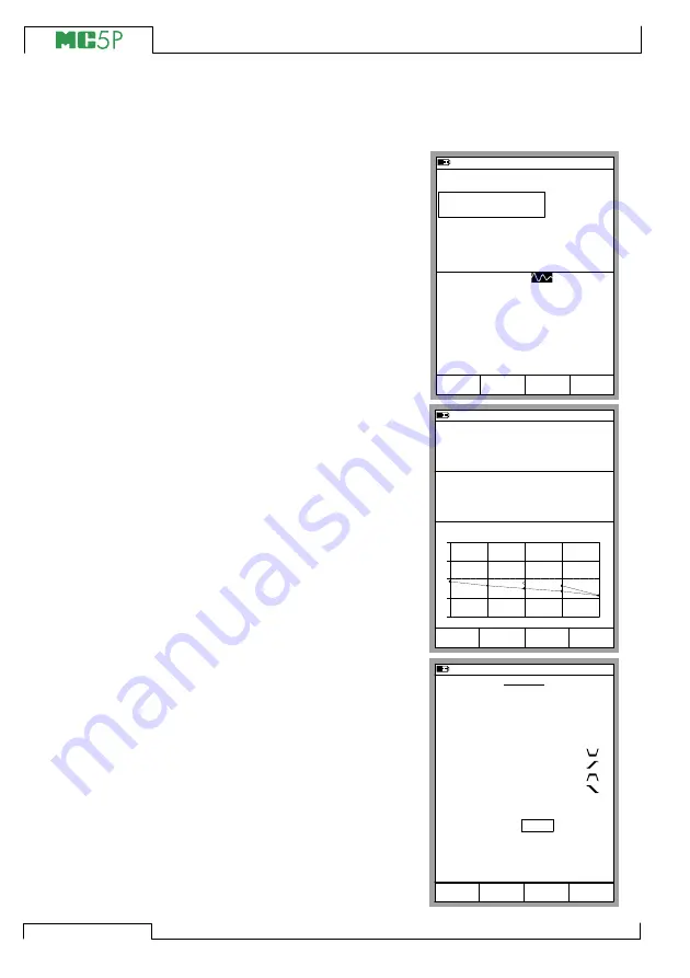
The Display Area
The layout of the display area varies according to the needs of the
active tasks/settings. The following
pictures give an overview of typical
elements seen in different display
area layouts.
Basic Measurement/Generation:
The display area is divided into two
windows with informative texts and
numeric measurement/generation
values.
A border surrounding a numeric
value indicates that the field is
editable. It is, e.g. a generation field
for entering generation values.
If several editable fields are visible,
choose the active field with the cur-
sor keys or the
B
/
Field
Function
Key.
Calibration:
The display area is divided into
three windows during a calibration.
The first window displays data re-
lated to the instruments input sig-
nal. The second corresponding
data related to the output signal.
The third window displays the er-
ror graph. The error graph is also
seen among calibration result data.
Configuration Window:
There are plenty of configuration
windows in MC5P. The picture be-
side is the configuration window for
Ramping settings.
The common thing for all configu-
ration windows is that they reserve
the whole display area for the con-
figuration fields.
Use the cursor keys to move be-
tween fields.
10.11.2003 15:04
1
Frequency
2
Current
ET: Frequency Gen.
E: Current Measurement
Amplitude [Vpp]
pos. square
kHz
5.00
1.00000
11.9837
Mode
Calibration
MENU
mA
Field
10.11.2003 15:04
Input
Error
0.40
Output
Pt100
α
385
°C (ITS90)
11.9925
-0.05 %of span
50.00
Pause
Accept
Force
+
0
-
0%
50%
100%
RTD Temperature [ET: Simul.]
Current [E: Meas.]
mA
10.11.2003 15:04
RAMPING
Cancel
Start
Quantity
Port
Wait in 0%
Rise Time
Wait in 100%
Fall Time
Repeats
0 = continuous
Range
0 %
100 %
Current
E: I(gen)
2
1
2
2
1
8.0000
16.0000
s
s
s
s
mA
Summary of Contents for MC5P
Page 36: ...28 General Empty ...


