


23
6-847718-00 Rev. B00
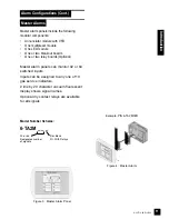
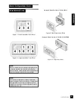
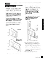
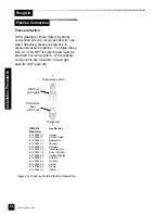
Alarm panel back box will be one of two
sizes. Height and depth of both size
boxes are identical. Refer to Figure 15
for dimensions of both boxes.
If alarm panel is configured with digital
display modules, sensor assemblies will
be included for connection to pressure /
vacuum pipeline.
Sensors may be located inside alarm
panel back box (local sensors) or outside
alarm panel back box (remote sensors).
If equipped with local sensors, copper
tubes will extend from top of back box to
be connected to pressure / vacuum
pipeline.
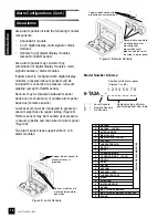
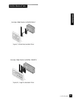
Alarm Panel Back Box
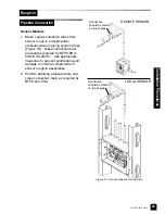
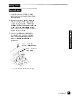
1. Prepare rough wall opening large
enough to accommodate alarm panel
back box. Alarm panel back box must
have rigid vertical members for
support on both left and right sides.
Power to alarm panel shall enter
through lower left or top left conduit
hole in back box.
2. Remove cardboard dust cover and
insert alarm panel back box into wall
opening. Secure with fasteners
suitable for vertical supports
(Figure 16).
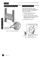
3. Mounting brackets on each side of
back box are adjustable and factory
preset for 5/8” thick drywall. After
drywall installation, front edge of back
box should be flush with finished
surface of wall. If needed, make any
necessary bracket adjustments at this
time (Figure 17).
4. Reinstall cardboard dust cover.
Figure 16: Back Box Mounting
Small box
Large box
Back Box details
simplified for clarity
Rough-In
Inst
allation
Procedures
Figure 15: Alarm Panel Back Box Dimensions
Summary of Contents for TotalAlert 2
Page 1: ...Installation Operation and Maintenance Instructions 6 847718 00 Rev B00...
Page 2: ......
Page 22: ...20 6 847718 00 Rev B00...
Page 97: ...95 6 847718 00 Rev B00 Figure 86 Clear Network Accepted Operation...
Page 99: ...97 6 847718 00 Rev B00 Operation Figure 89 Event Log Cleared...
Page 101: ...99 6 847718 00 Rev B00 Operation Figure 91 Transfer Setup Figure 92 Transfer Setup Complete...
Page 129: ...127 6 847718 00 Rev B00 Troubleshooting Guide Troubleshooting...
Page 130: ...128 6 847718 00 Rev B00...
Page 139: ...137 6 847718 00 Rev B00 Replacement Parts Notes...
Page 143: ......
Page 144: ...2007 BeaconMed s All rights reserved 6 847718 00 Rev B00...