background image

44

4. BIOS SETUP

4.4


BIOS Features Setup Menu

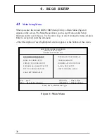
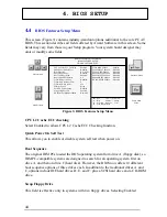
This screen (Figure 3) contains industry-standard options additional to the core PC AT
BIOS. This section describes all fields offered by Award Software in this screen. Some
fields may vary from those in your Setup program. Your system board designer may
omit or modify some fields.

CPU L2 Cache ECC checking

Select Enabled to allows CPU L2 Cache ECC Checking function.

Quick Power On Self Test

This allows you to enable or disable system self test when power on.

Boot Sequence

The original IBM PCs loaded the DOS operating system from drive A (floppy disk), so
IBM PC-compatible systems are designed to search for an operating system first on
drive A, and then on drive C (hard disk). However, the BIOS now offers 10 different
boot sequence options of three drives each. In addition to the traditional drives A and
C, options include IDE hard drives D, E, and F; plus a SCSI hard drive and a CD-ROM
drive.

Swap Floppy Drive

This field is effective only in systems with two floppy drives. Selecting Enabled

ROM PCI/ISA BIOS (2A69KB3M)

BIOS FEATURES SETUP

AWARD SOFTWARE, INC.

Esc :  Quit            

↑→←↓

  :  Select Item

F1   :  Help            PU/PD/+/-  :  Modify
F5   :  Old value     (Shift) F2     :  Color
F7   :  Load Setup Defaults

Move to items

Exit to Main

Menu

Modify values

Enter Sub-Menu

: Enabled
: Disabled
: A, C, SCSI
: Disabled
: Enabled
: On
: Disabled
: 6
: 250
: Setup
: Disabled
: Enabled
: Non-OS2

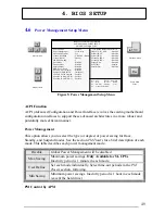
Video BIOS Shadow
C8000-CBFFF Shadow
CC000-CFFF Shadow
D0000-D3FFF Shadow
D4000-D7FFF Shadow
D8000-DBFFF Shadow
DC000-DFFFF Shadow

CPU L2 Cache ECC Checking
Quick Power On Self Test
Boot Sequence
Swap Floppy Drive
Boot Up Floppy Seek
Boot Up NumLock Status
Typematic Rate Setting
Typematic Rate (Chars/Sec)
Typematic Delay (Msec)
Security Option
PCI/VGA Palette Snoop
Assign IRQ For VGA
OS Select For DRAM >64MB

: Enabled
: Disabled
: Disabled
: Disabled
: Disabled
: Disabled
: Disabled

Figure 3: BIOS Features Setup Menu

Summary of Contents for GT440ZX

Page 1: ...1 Advanced Pentium II Motherboard GT440ZX USER S MANUAL ...

Page 2: ...nd Pentium are registered trademarks of Intel Corporation IBM and OS 2 are registered trademarks of International Business Machines AWARD is a registered trademark of Award Software Inc Responsibility This manual is provided As is with no warranties of any kind either expressed or implied including but not limited to the implied warranties or conditions of this product s fitness for any particular...

Page 3: ...ovisions of the 1994 Regulations FCC Compliance FCC stands for Federal Communications Commission This product complies with FCC Rules Part 15 and has been tested and complied with the EMI rules by a certified body In normal operation there shall be no harmful interference caused by this device nor shall this devise accept any interference received including interference that may cause undesired op...

Page 4: ...pter 3 Install the CPU by correctly aligning the CPU with the slot1 as noted in the motherboard diagram Once aligned press down on the CPU gently but firmly and lock it Next install the 3 3 volt unbuffered SDRAM into the 168 pin DIMMs See Sec 3 2 Sec 3 3 Set CPU speed in according to Sec 3 2 After completing the above steps install any expansion Cards PCI ISA into riser card and have the riser car...

Page 5: ...5 EASY INSTALLATION ...

Page 6: ... DIMM Module Combinations 21 3 4 EXPANSION SLOTS 22 3 5 CONNECTORS 23 3 5 1 Primary IDE Connector J21 39 pin block 23 3 5 2 Secondary IDE Connector J18 39 pin block 23 3 5 3 Floppy Drive Connector J23 33 pin block 24 3 5 4 Power Input Connector J20 20 pin block 24 3 5 5 Front Panel connectors 25 3 5 6 Back Panel Connectors 27 Additional Connectors 30 4 BIOS SETUP 36 4 1 HOW TO ENTER BIOS SETUP 36 ...

Page 7: ...SETUP MENU 44 4 5 CHIPSET FEATURES SETUP MENU 47 4 6 POWER MANAGEMENT SETUP MENU 49 4 7 PCI CONFIGURATION SETUP MENU 52 4 8 INTEGRATED PERIPHERALS MENU 53 4 9 LOAD SETUP DEFAULTS 56 4 10 USER PASSWORD 56 4 11 IDE HDD AUTO DETECTION 56 4 12 SAVE EXIT SETUP 56 4 13 EXIT WITHOUT SAVING 57 ...

Page 8: ...tallation procedure presented on the EASY INSTALLATION Page and refer to the section number following each step if you require more detailed instructions Check Your Device Items The standard package should contain following items marked with a 4 If you find any these items missing or damaged Please contact your retailer 4The GT440ZX motherboard 4Universal Retention Mechanism Support both Pentium I...

Page 9: ...9 2 FEATURES 2 2 2 F F FE E EA A AT T TU U UR R RE E ES S S Photo Of The Motherboard ...

Page 10: ...tegrated PCI Bus Master IDE Controller Chip with Ultra DMA33 capabilities Up to four IDE devices can be supported using the two onboard IDE connectors Also supported is PIO Modes 3 4 Bus Master IDE DMA Mode 2 and Enhanced IDE devices such as Tape Backup machines and CD ROMs Either the 5 25 inch or 3 5 inch 1 44MB or 2 88MB floppy drives can be used without requiring an external card Additionally F...

Page 11: ...ne out Line in Mic In l 1 MIDI Game port 1 CD in 1 Modem in 1 Aux in l SPDIF Interface support Additional features l Wake On LAN header l Keyboard power on function l Modem Ring up function l Front USB header optional l Hardware Monitor Capability optional Expansion Slots l 1 AGP 1 ISA 2 PCI expansion slots and one shared PCI Mechanical l This motherboard complies with the Micro ATX Form Factor sp...

Page 12: ...out Main Parts ISA Slot Modem in S PDIF Clear Password Clear CMOS WOL CD in Aux in Mic in Line in Line out Game MIDI COM2 Printer COM1 USB 2 PS 2 2 DIMM Sockets CPU FAN CPU Slot CPU Freq Ratio Front Panel Ring In PCI Slots Speaker USB Select AGP Slot Chassis FAN FDD Front USB Pri HDD Sec HDD ATX Power ...

Page 13: ...ec 3 5 6 One Game Port Sec 3 5 6 Line out Sec 3 5 6 Line in Sec 3 5 6 MIC in Sec 3 5 6 Expansion Slots Sockets SEC CPU Slot Sec 3 2 DIMM Sockets Sec 3 3 ISA PCI AGP Slots Sec 3 4 Power IDE FDD Connectors IDE connectors Sec 3 5 1 Power connector Sec 3 5 4 FDD connector Sec 3 5 3 Additional Connectors Chassis Fan Sec 3 5 7 Clear Password Sec 3 5 7 Clear CMOS Sec 3 5 7 IrDA Sec 3 5 7 CPU Fan Sec 3 5 ...

Page 14: ...rounded anti static surface component side up Immediately inspect the board for damage Due to shifting during shipping it is suggested that the installer press down on the entire socket ICs to ensure they are properly seated Do this only with the board placed on a firm flat surface 4 During configuration and installation touch a grounded surface frequently to discharge any static electrical charge...

Page 15: ...se J2 USB1 USB2 J3 COM2 J4 COM1 J5 Line in Line out and Mic in J6 Game MIDI J7 Printer J8 MODEM In J9 SPDIF J10 CD IN J11 PCI 3 J12 PCI 2 J13 PCI 1 J14 Front USB Header J15 AGP Slot J16 WOL Wake On LAN J17 CPU Fan Header J18 Secondary IDE J19 Ring IN J20 ATX Power J21 Primary IDE J22 Front Panel headers J23 Floppy J24 Speaker J25 Chassis Fan J26 AUX IN JP1 CPU Speed Jumper JP2 Clear CMOS jumper JP...

Page 16: ...over When mounted in Slot1 the processor is secured by two retention mechanism attached to the motherboard 3 2 1 Install CPU Please follow the below steps to install your CPU and configure the speed in according to Processor Jumper Setting List First please ensure the following parts you received with this motherboard One Pentium II URM Universal Retention Mechanism and four Lock Pins Usually the ...

Page 17: ... two locks inward and insert the CPU into Retention Mechanism Press the top of CPU gently but firmly until it is fully inserted Warning It is strongly recommended that a heatsink and CPU cooling fan be used to prevent the CPU from overheating Applying a thermal of jelly between the 1 Unfold the Retention Mechanism 2 Place the Retention Mechanism over CPU Slot 3 Push 4 lock pins into holes to fix R...

Page 18: ...settings for your CPU Please refer to the following figure and tables to carefully finish it CPU BUS Speed 7 5 3 1 8 6 4 2 Now follow the below table to configure your CPU settings Setting CPU BUS Speed JP1 Intel CPU BUS Pin 1 2 Pin 3 4 Pin 5 6 Pin 7 8 X3 5 233 66 MHz X4 266 66 MHz X4 5 300 66 MHz X5 333 66 MHz X5 5 366 66 MHz X6 400 66 MHz X6 5 433 66 MHz ...

Page 19: ...466 66 MHz JP1 Intel CPU BUS Pin 1 2 Pin 3 4 Pin 5 6 Pin 7 8 X3 300 100 MHz X3 5 350 100 MHz X4 400 100 MHz X4 5 450 100 MHz X5 500 100 MHz Note Host Bus Frequency 66 MHz or 100 MHz will be auto detected by this motherboard ...

Page 20: ...M socket Step2 Insert the DIMM module into the DIMM socket vertically After inserting the DIMM module completely into the socket push up on the socket latches securing the DIMM into place If pin 1 of the DIMM module does not line up with pin 1 of the socket the DIMM module will not be inserted correctly into the socket Be careful not to misfit the DIMM Module into DIMM sockets in wrong direction T...

Page 21: ...figure to select one way to insert your DIMM for example To select 1 out of 6 items empty 8MB 16MB 32MB 64MB 128MB in DIMM1 Then repeat again in DIMM2 to go through your own path A total of 36 combinations ensure you can insert your DIMM modules any way you prefer DIMM 1 64MB DIMM 2 16MB Total 64 16 80 MB Select Select DIMM 1 DIMM 2 Empty 64MB 32MB 16MB 8MB 64MB 32MB 16MB 8MB Empty 128MB 128MB ...

Page 22: ...ds and are fully supported by the PCI 2 1 specification The Accelerated Graphics Port AGP or A G P is a high performance interconnect targeted at 3D graphical display applications and is based on a set of performance extensions or enhancements to the PCI bus AGP interface specification Rev 1 0 compliant To install expansion cards please read the expansion card s documentation for instructions and ...

Page 23: ...e mode as indicated in the device s manual 3 5 2 Secondary IDE Connector J18 39 pin block This connector supports two secondary channel IDE devices as well as the 120MB Floppy drives via a ribbon cable When two IDE devices are installed using the secondary IDE connector make sure that the second IDE device is adjusted to slave mode as instructed in the device s manual 1 2 40 39 1 2 40 39 Pri IDE S...

Page 24: ...ion to the floppy drive is via a header J19 The floppy disk interface includes 48mA drivers and inputs on the drive interface 3 5 4 Power Input Connector J20 20 pin block This connector supports a Micro ATX power supply When connecting make sure the lock key matches the hook attached on a power supply cable The power cord should be unplugged when you connect it 1 2 34 33 1 2 34 33 ...

Page 25: ...module mounts in a small opening on the system case that supports this feature The efficient distance is 100cm and the transfer rate is 115 200 bits sec Reset Switch Connector 2 pin This connector supports the front panel case mounted reset button It is advised that the reset switch be used for rebooting the system in order to extend the life of the system s power supply HDD IDE LED Connector 2 pi...

Page 26: ...ATX case mounted Power Switch which in turn supports System Suspend function When the BIOS sets the Power Button function to Delay 4 sec the system can be set to the suspended mode once you push the power switch for no longer then 4 seconds If the power switch is pushed down for over 4 seconds the system will be totally Power Off When the BIOS setting sets the Delay 4 second to Instant off then Po...

Page 27: ...niversal Serial Bus USB Ports J2 The motherboard has two USB connectors USB devices provide a more convenient operating environment and improve data transferring capacity True Plug Play this new bus technology will support over 127 different peripherals through a Hub Printer Game MIDI PS 2 USB COM1 COM2 Audio headers Mouse Keyboard USB2 USB1 ...

Page 28: ...dary LPT address or the primary LPT address through BIOS if another parallel port is installed Serial Port COM J4 J3 The motherboard has two serial ports The electrical characteristics are compliant with the EIA 232 D Serial Communications Specifications The serial ports may be remapped over other installable serial ports or disabled through the BIOS Printer Parallel COM1 COM2 ...

Page 29: ...stick or MIDI device Audio Port Line in Line out MIC in J5 The GT440ZX also provides external sound system through a user accessible stereo jack connector soldered to the PWA This jack allow the connection of self amplified speakers Line in voice input and MIC in voice input GAME MIDI Line out Line in Mic in ...

Page 30: ...n password is set in the BIOS it can be cleared by inserting a cap over pin 1 2 of the Clear Password header Clear CMOS JP2 2 pin You can insert a cap over pin 1 2 of the Clear CMOS header to clear the CMOS data and reload the default settings Chassis Fan J25 3 pin This header can supply power for Chassis Fan which may be mounted inside your case to cool down your system components If your chassis...

Page 31: ...r remote wakeup of the computer through a network WOL requires a PCI add in network interface card NIC with remote wakeup capabilities The remote wakeup header on the NIC must be connected to the onboard Wake on LAN header For Wake on LAN the 5 V standby line for the power supply must be capable of delivering 5V 5 at 720mA CPU Fan J17 3 pin Your Pentium Cartridge may have an attached heatsink and ...

Page 32: ...pplications such as speakerphones fax modems and answering machines S PDIF J9 2 pin This connector is the digital link between the motherboad and your audio devices such as CD player or DAT recorder It allows the digital transmission of audio data in SPDIF Sony Philips Digital Interface Format CD IN Header J10 4 pin Black A connector is available for audio input from CD ROM drives AUX IN Header J2...

Page 33: ... system case 4 Connect the power supply cord into an outlet of power supply 5 Connect Monitor signal cable to system VGA port and the monitor power cord to power outlet 6 Now turn on monitor and system power After Power on The power LED on the front panel of the system case will light For ATX power supplies the system LED will light when the ATX power switch is pressed The system will then do a po...

Page 34: ...34 3 INSTALLATION SETUP ...

Page 35: ...35 3 INSTALLATION ...

Page 36: ... of configuring your system using the BIOS Setup 4 1 How To Enter BIOS Setup The AWARD BIOS is immediately activated when you first turn on the computer The BIOS reads system configuration information in CMOS RAM and begins the process of checking the system and configuring it through the power on self test POST When these preliminaries are finished the BIOS seek an operation system on the data st...

Page 37: ... default F10 Save all the CMOS changes only for Main Menu 4 1 2 Getting Help Press F1 to pop up a small help window that describes the appropriate keys to use and the possible selections for the highlighted item To exit the Help Window press Esc or the F1 key again 4 1 3 In Case of Problems If after making and saving system changes with Setup you discover that your computer no longer is able to bo...

Page 38: ...r the sub menu A brief description of each highlighted selection appears at the bottom of the screen ROM PCI ISA BIOS 2A69KB3M CMOS SETUP UTILITY AWARD SOFTWARE INC STANDARD CMOS SETUP BIOS FEATURES SETUP CHIPSET FEATURES SETUP POWER MANAGEMENT SETUP PNP PCI CONFIGURATION LOAD SETUPDEFAULTS INTEGRATED PERIPHERALS USER PASSWORD IDE HDD AUTO DETECTION SAVE EXIT SETUP EXIT WITHOUT SAVING Esc Quit Sel...

Page 39: ...t depend on the integrated peripherals controller in your system Supervisor User Password Setting Change set or disable a password In BIOS versions that allow separate user and supervisor passwords only the supervisor password permits access to Setup The user password generally allows only power on access IDE HDD Auto Detection Automatically detect and configure IDE hard disk parameters Load Setup...

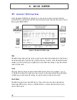
Page 40: ...PgDn key to increment the setting or type the desired value into the field Hard Disks The BIOS supports up to four IDE drives This section does not show information about other IDE devices such as a CD ROM drive or about other hard drive types such as SCSI drives Date mm dd yy Wed Jun 4 1997 Time hh mm ss 8 53 11 HARD DISKS TYPE SIZE CYLS HEAD PRECOMP LANDZ SECOTR MODE Primary Master Auto 0 0 0 0 ...

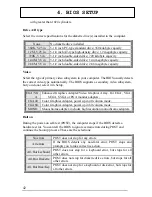
Page 41: ...e type has a specified number of cylinders number of heads write precompensation factor landing zone and number of sectors Drives whose specifications do not accommodate any pre defined type are classified as type USER Size Disk drive capacity approximate Note that this size is usually slightly greater than the size of a formatted disk given by a disk checking program Cyls Number of cylinders Head...

Page 42: ...p EGA VG A Enhanced Graphics Adapter Video Graphics Array For EGA VGA SEGA SVGA or PGA monitor adapters CGA 40 Color Graphics Adapter power up in 40 column mode CGA 80 Color Graphics Adapter power up in 80 column mode MONO Monochrome adapter includes high resolution monochrome adapters Halt on During the power on self test POST the computer stops if the BIOS detects a hardware error You can tell t...

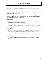
Page 43: ...ay contain up to 64 MB 128 MB or more Base Memory Typically 640 KB Also called conventional memory The DOS operating system and conventional applications use this area Extended Memory Above the 1 MB boundary Early IBM personal computers could not use memory above 1 MB but current PCs and their software can use extended memory Other Memory Between 640 KB and 1 MB often called High memory DOS may lo...

Page 44: ...raditional drives A and C options include IDE hard drives D E and F plus a SCSI hard drive and a CD ROM drive Swap Floppy Drive This field is effective only in systems with two floppy drives Selecting Enabled ROM PCI ISA BIOS 2A69KB3M BIOS FEATURES SETUP AWARD SOFTWARE INC Esc Quit Select Item F1 Help PU PD Modify F5 Old value Shift F2 Color F7 Load Setup Defaults Move to items Exit to Main Menu M...

Page 45: ...lay are irrelevant Keystrokes repeat at a rate determined by the keyboard controller in your system When Enabled you can select a typematic rate and typematic delay Typematic Rate Chars Sec When the typematic rate setting is enabled you can select a typematic rate the rate at which character repeats when you hold down a key of 6 8 10 12 15 20 24 or 30 characters per second Typematic Delay Msec Whe...

Page 46: ... CPU can read it through the 16 bit or 32 bit DRAM bus Firmware not shadowed must be read by the system through the 8 bit X bus Shadowing improves the performance of the system BIOS and similar ROM firmware for expansion peripherals but it also reduces the amount of high memory 640 KB to 1 MB available for loading device drivers etc Enable shadowing into each section of memory separately Many syst...

Page 47: ...at F0000h FFFFFh resulting in better system performance However if any program writes to this memory area a system error may result Video RAM Cacheable Select Enabled allows caching of the Video RAM resulting in better system performance However if any program writes to this memory area a system error may result ROM PCI ISA BIOS 2A69KB3M CHIPSET FEATURES SETUP AWARD SOFTWARE INC Esc Quit Select It...

Page 48: ...erated Graphics Port AGP aperture The aperture is a portion of the PCI memory address range dedicated for graphics memory address space Hose cycles that hit the aperture range are forwarded to the AGP without any transiation See www agpforum org for AGP information Power Up State It specifies how the computer responds following a power failure Stay Off keeps power off until power button pressed La...

Page 49: ... Minimum power savings Inactivity period is 1 hour in each mode except the hard drive PM Control by APM ROM PCI ISA BIOS 2A69KB3M POWER MANAGEMENT SETUP AWARD SOFTWARE INC Esc Quit Select Item F1 Help PU PD Modify F5 Old value Shift F2 Color F7 Load Setup Defaults Move to items Exit to Main Menu Modify values Enter Sub Menu Enabled User Devine Yes V H SYNC Blank Standby 3 Disabled Disabled Disable...

Page 50: ...r your video subsystem to select video power management values Blank Screen System only writes blanks to the video buffer Video Off After As the system moves from lesser to greater power saving modes select the mode in which you want the monitor to blank Modem Use IRQ This determines the IRQ in which the MODEM can use The choices 3 4 5 7 9 10 11 NA Doze Mode When enabled and after the set time of ...

Page 51: ...t Off Delay 4 Sec PowerOn By Ring WOR This item allows you to power on the system from Ring by selecting Enabled The choice Enabled Disabled PowerOnBy LAN WOL This item allows you to power on the system from LAN by selecting Enabled The choice Enabled Disabled Reload Global Timer Events IRQ 3 7 9 15 NMI Primary IDE0 Primary IDE1 Floppy Disk Serial Port Parallel Port When Enabled an event occurring...

Page 52: ...Data Normally you leave this field Disabled Select Enabled to reset Extended System Configuration Data ESCD when you exit Setup if you have installed a new add on and the system reconfiguration has caused such a serious conflict that the operating system cannot boot ROM PCI ISA BIOS 2A69KB3M PNP PCI CONFIGURATION SETUP AWARD SOFTWARE INC Esc Quit Select Item F1 Help PU PD Modify F5 Old value Shift...

Page 53: ...support The Choice Auto Disabled On chip Primary IDE The chipset contains a PCI IDE interface with support for two IDE channels Select Enabled to activate the primary IDE interface Select Disabled to deactivate this interface The choice Enabled Disabled ROM PCI ISA BIOS 2A69KB3M INTEGRATED PERIPHERALS SETUP AWARD SOFTWARE INC Move to items Exit to Main Menu Modify values Enter Sub Menu Disabled Au...

Page 54: ...system has a floppy disk controller FDC installed on the system board and you wish to use it If you install and in FDC or the system has no floppy drive select Disabled in this field The choice Enabled Disabled Onboard Serial Port 1 Port 2 This item allows you to determine access onboard serial port 1 port 2 controller with which I O address The choice 3F8 IRQ4 2E8 IRQ3 3E8 IRQ4 2F8 IRQ3 Disabled ...

Page 55: ... 7 ECP Mode Use DMA Select a DMA channel for the parallel port for use during ECP mode The choice 3 1 Onboard Audio Device This system embeds an audio chip to feature the excellent audio function Select Enabled to use the onboard audio system or Disabled to abort ...

Page 56: ... time press Esc In the Security Option item in the BIOS Features Setup screen select System or Setup System Enter a password each time the system boots and whenever you enter Setup Setup Enter a password whenever you enter Setup NOTE To clear the password simply press Enter when asked to enter a password Then the password function is disabled 4 11 IDE HDD Auto Detection BIOS setup will display all...

Page 57: ...57 4 BIOS SETUP 4 13 Exit Without Saving Abandon all CMOS value change without saving ...

Reviews: