background image

3


TABLE OF CONTENTS


FACTORY CONTACT INFORMATION  ………...………….…………..   2 

TABLE OF CONTENTS …………………..……………….……………..   3 

WELCOME TO LIL’ TICKET MONSTER ……….…….………………..   4 

GAME SPECIFICATIONS  …………….………………………………..   5 

SAFETY PRECAUTIONS ……………………...………………………..   6 

REMOVABLE MARQUEE ……..………..………………..……………..   6 

GAME SET UP …………………………………………………..….  7 

-

 12 

CARD SWIPE INSTALLATION ………………………………………..   13 

AVAILABLE BLANKING PLATES ……………………………………..   13 

GAME  PLAY  THEORY  OF  OPERATION  ……………………………    14 

MAIN MENU FUNCTIONS …………………………………………….    15


AUDIO  SETTINGS  ……………………………………….……..      16 


PAYOUT SETTINGS MENU …………………………………….   17    


TICKET PATTERNS …………………………………………  18 

-

 19 


GAME  SETTINGS  MENU  ………….……...………….………    20


STATISTICS MENU  ……………………………………………..   20 


DIAGNOSTIC MENU  ……………...……………………..……..   21  

HOW TO LOCATE CIRCUIT BOARDS  …………………………..….   22  

DIPSWITCH SETTINGS ……………………………………………….   22 

CIRCUIT BOARD LAYOUT ……………………………………………   23 

WIRING DIAGRAMS ………………………………………………   24 

-

 28 

TROUBLESHOOTING GUIDE …………….…………….……….   29 

-

 34 

BILL ACCEPTOR DIAGNOSTICS ……………………………………   34 

POWER SUPPLY DIAGNOSTICS ……………………………………   35 

HOW TO CHANGE SOFTWARE ………………….………………….   36  

I/O AUX BOARD PINOUT …………….…………..……………………   36 

HOW  TO  OPEN  THE  FRONT  PLEXI  …………………………….      37 

HOW TO REMOVE ARROW SENSOR  …………………………….   37 

HOW  TO  ADJUST  ARROW  SENSOR  …………………………….      38 

HOW  TO  ADJUST  BRAKE  TENSION  …………………………….      38 

HOW  TO  REMOVE  HOME  SENSOR  …………………………….      39 

HOW  TO  REPLACE  MONITOR    ………...………………….…..…      39 

HOW TO REPLACE SOLENOID  ………...………………….….   40 

-

 42 

HANDLE ASSY EXPLODED VIEW  …………….……………………   43 

DECAL DIAGRAM ………………………………………………………   44 

PARTS LIST …………………...……………………………....……  45 

-

 46 

PARTS PICTURES …………………………………………………  47 

-

 49 

MAINTENANCE LOG …………………………………………………..   50 

TECHNICAL SUPPORT ………………………………………………..   51  

WARRANTY ……………………………………………………………..   52 


Manual Revision 1/26/2022 

-

 Software Version: 1.0


Summary of Contents for Lil Ticket Monster

Page 1: ...SERVICE MANUAL PLACE SERIAL NUMBER LABEL HERE...

Page 2: ...e latest game information new product launches early notification of parts specials updates of retro fit parts software upgrades best practices and more Visit baytekent com and enter your email to sig...

Page 3: ...TO LOCATE CIRCUIT BOARDS 22 DIPSWITCH SETTINGS 22 CIRCUIT BOARD LAYOUT 23 WIRING DIAGRAMS 24 28 TROUBLESHOOTING GUIDE 29 34 BILL ACCEPTOR DIAGNOSTICS 34 POWER SUPPLY DIAGNOSTICS 35 HOW TO CHANGE SOFTW...

Page 4: ...to all age groups creating multi generation appeal to anyone that steps through your doors Please take a moment to read through this manual and be sure to contact our factory if you have any question...

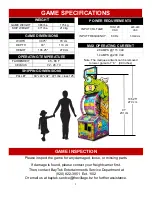
Page 5: ...IFICATIONS WEIGHT GAME WEIGHT 386 lbs 175 kg SHIP WEIGHT 471 lbs 214 kg GAME DIMENSIONS WIDTH 30 75 79 cm DEPTH 43 110 cm HEIGHT 106 25 270 cm OPERATING TEMPERATURE FAHRENHEIT 45 80 F CELSIUS 7 2 26 7...

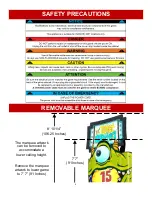
Page 6: ...he marquee artwork can be removed to accommodate a lower ceiling height Remove the marquee artwork to lower game to 7 7 91 Inches SAFETY PRECAUTIONS REMOVABLE MARQUEE 8 10 1 4 106 25 Inches 7 7 91 Inc...

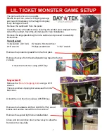
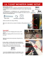
Page 7: ...lock the front door using a H95 key Tools Needed 1 step ladder 4 6 foot 2 square bit screwdriver 9 16 wrench Phillips screwdriver 11 32 wrench Remove the hardware kit Part A5KIT LTM wood blocks and se...

Page 8: ...exi wrap 2 of A5SCPH230 and 2 of A5NULO030 used to secure plexi wrap below monitor 1 of A5BOHH060 1 of A5WASI020 and 1 of A5WAFL060 are to be saved with the wood blocks and used to support the wheel i...

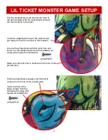
Page 9: ...this on both arms of the marquee Install the printed plexi wrap Remove the clear protective film from both sides of the printed plexi wrap The idea is to secure one screw into the left side of the ple...

Page 10: ...screw in this location Line up the printed plexi with this pilot hole and insert 1 of the black screws from the hardware kit using a 2 square bit screwdriver Make sure the bolt hole is centered in the...

Page 11: ...from the hardware kit using a 2 square bit screwdriver in both the left side and right side printed plexi wrap There are a total of 15 screws in each side A5SCPH151 If the plexi bulges in spots it ma...

Page 12: ...and turn on the rocker switch on the power strip along the right side of coin box The rocker switch is located behind the 1st power cord on the strip Install the 2 center bolts and nuts under the mon...

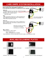
Page 13: ...ructions to make full use of this capability Menu Changes Enter menu go to Payout Menu Verify Credits set to 1 Verify Card Reader set to Enabled Check dipswitches on the I O Aux Board in the front of...

Page 14: ...The Good Spin wheel speed is measured by the Wheel Encoder Sensor located in the arrow in the right front of the wheel This Wheel Encoder Sensor also detects the notched edge around the right edge of...

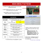
Page 15: ...u Diagnostics Press MENU SELECT to enter the Diagnostic Menu Exit Press MENU SELECT button to exit menu Default settings are highlighted in yellow Software versions are shown on the bottom left corner...

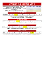
Page 16: ...ding scale OFF means no game play volume GAME VOLUME 3 4 5 OFF 1 2 6 7 8 9 10 ATTRACT VOLUME 3 4 5 OFF 1 2 6 7 8 9 10 Sets the attract volume on a sliding scale OFF means no attract volume ATTRACT TIM...

Page 17: ...E CARD TAP CARD INSERT CREDITS Disabled 1 2 3 4 5 24 25 FIXED TICKETS Sets the amount of tickets that will be given if the player only if Ticket Pattern is set to Fixed Tickets Sets the ticket pattern...

Page 18: ...ix 40 60 There are 4 base ticket patterns to choose from These base patterns can be adjusted by adding cover up decals to the wheel over the minor and major bonus values Base ticket values and minor a...

Page 19: ...he wheel Order part AADE22510 TICKET PATTERNS There are 4 base ticket patterns to choose from These base patterns can be adjusted by adding cover up decals to the wheel over the minor and major bonus...

Page 20: ...the SELECT button to go back to the main menu Default settings are highlighted in yellow below ENTERTAINMENT ONLY ON will not dispense tickets OFF ON STATISTICS MENU Scroll through the options by pre...

Page 21: ...and allow it to coast to a stop This will show Brake OK when brake is set correctly Revolutions Per Minute of wheel as it s turning RESET TO DEFAULTS All Menu Options will change to the Factory Defaul...

Page 22: ...en It will round up odd amounts of tickets X 5 DISABLES LOW TICKET INPUT Disables the low ticket message on screen This option should be enabled when using a card swipe system X 6 NOT USED 7 NOT USED...

Page 23: ...el Control AACE26011 Arrow Sensor A5CBL5900 USB Commu nication from Motherboard AACE26007 Home Sensor AACE26000 Solenoid AACE26015 Power in from Power Dist Bd Normally Red and Orange LEDs are on solid...

Page 24: ...k Wires 5 VDC when notch opto is blocked 0 VDC when sees a notch White Black Wires 5 VDC when enabled and tickets are trying to dispense FRONT DOOR WIRING DIAGRAM AASW200 Low Ticket Switch Wired Norma...

Page 25: ...2 VDC between the Orange Blue wires White Blue 5VDC when blocked 0 VDC when sensor eye sees a notch Green Blue 5VDC when blocked 0 VDC when sensor eye sees a notch A5CBL5900 Small USB communication to...

Page 26: ...0 AACE26033 Console Edge RGB Lights AACE26032 Plunger Accent RGB Lights AACE22505 AACB8001 LTM Light Board AACE22506 Eyeball Color Lights Normally Red and Yellow LEDs are on solid AACE26017 Power to 8...

Page 27: ...re on solid AACB9605 CBL I O Aux Board Red and yellow LEDs are normally flashing all the time Green Power LED should be flashing AACB8001 LTM Light Board Normally Red and Yellow LEDs are on solid A5MO...

Page 28: ...top of game Outlet Strip A5OU5000 On Off Rocker Switch Line Filter A5FI9010 Power In Cord From Wall A5CORD5 AC Bleeder Board AACB15001 AC Power In cable AACE22500 A5PS1021 Power Supply AAMB12 HD LTM M...

Page 29: ...ibution Board AACB5156 Power supply unplugged Rocker Switch Power supply shutting down because of 12 V overload Faulty power supply Faulty Power Dist Board Dollar Bill Acceptor not functioning Ensure...

Page 30: ...and comes out of speaker If Yes then motherboard is faulty If No then Audio Amplifier Board AACB9600A may be faulty Replace speaker AACE8811 TROUBLESHOOTING GUIDE White lights in marquee do not work 1...

Page 31: ...u from Diagnostic Menu and verify number of the screen matches the number on the wheel Change Ticket Pattern setting in menu if needed Refer to Home Sensor not working properly section Refer to Encode...

Page 32: ...m opto sensor to I O board Refer to wiring diagram Cable CE26007 Enter Diagnostic Menu Wheelboard area to see if game recognizes sensor Screen will flash Home Sensor when sensor is seen Once per revol...

Page 33: ...ive 12 Volts DC Replace solenoid assembly if needed AASO26001 If it is off then check 12 5 Volts DC coming into board on cable CE26015 from Power Distribution Board If solid on then it is not communic...

Page 34: ...crimp to ensure good connection Check connections from menu buttons to I O board Check continuity on wires AAPB2700 CE26012 Replace I O Aux Board AACB9605A CBL BILL ACCEPTOR DIAGNOSTICS Determine if...

Page 35: ...ort If power supply still does not power on then replace power supply A5PS1021 or replace motherboard AAMB12 HD LTM 1 Verify AC power to game Check power strip in front door The rocker switch should b...

Page 36: ...l white plastic spacer under the screw Leave this on the board the M 2 drive will rest on top of this spacer New Software Installation The hard drive contains all the information about the game Credit...

Page 37: ...wdriver Loosen but do not remove the 1 bolt using a Phillips screwdriver Remove the Win arrow metal plate by sliding to the left Remove the 2 Phillips screws from the top rail The arrow sensor assembl...

Page 38: ...that pushes against the wheel to slow and stop the wheel after a good spin speed has been reached Too tight of brake tension will stop the wheel quickly and may allow a skilled player to master the t...

Page 39: ...e lower end of the wood block using a 7 16 wrench The wood block with the sensor attached will now slide off the top post The sensor can now be cleaned or replaced if needed by removing the 2 Phillips...

Page 40: ...frame using a 1 2 wrench and remove the bolts HOW TO REPLACE SOLENOID The wheel must be swung outward to access and replace the solenoid assembly Tools Needed Phillips Screwdriver 2 Square bit 7 16 wr...

Page 41: ...cks that are shipped with the game in the coin box with a bolt lock washer and washer Slide the long narrow piece into the slot of the other piece to create a shelf Install the bolt lock washer and wa...

Page 42: ...bolt and star washer using a 7 32 Allen wrench Remove the metal plate and remove the white plastic spacer from the wheel shaft The solenoid assembly AASO4010 can now be removed from the wheel shaft U...

Page 43: ...420 A5ME8812 A5ME8812 A5RICZ010 A5ME4417 A5ME4420 A5PICZ010 A5WAFL080 A5WAFL080 A5PICZ010 A5WAFL080 A5PICZ010 A5WAFL080 A5PICZ010 A5CO4400 A5ME8816 WAWM0036 AAME4415 A5SCHH030 A5WAFL050 AATURU001 A5PI...

Page 44: ...22511 A5DE22510 A5DE22512 A5DE22513 A5DE22514 A5DE22515 A5DE22506 A5DE22504 A5DE22516 A5DE22523 A5DE22509 PARTS NOT VISIBLE A5DE22503 Left Bottom Side Cabinet Decal A5DE22505 Left Cabinet Rail Decal A...

Page 45: ...et Cover Up Wheel Decal Set A5DE22508 Decal Wheel Side Left A5DE22509 Decal Wheel Side Right A5DE22510 Decal Pointer Arrow A5DE22511 Decal Plunger Wrap A5DE22512 Printed Plexi Plunger Base A5DE22513 P...

Page 46: ...cket AACE26013 CB9605 Board to Coin Door and Tickets AACE26014 Power Distribution Board to CB9605 AACE26015 Power Distribution Board to CB26000 AACE26017 Power Distribution to CB8001 Power AACE26018 P...

Page 47: ...AASW220 AAWH26000 AABK1013 AACO1020 AAHA26000 AAPO26000 AASO26001 AATURU001 W5HG1025 W5HG1065 W5KE5000 A5DE0042 A5DE0044 A5DE22500 A5DE22501 A5DE22502 A5DE22503 A5DE22504 A5DE22505 A5DE22506 AADE22510...

Page 48: ...5ME26010 A5ME26011 A5ME26012 A5ME26013 A5ME4167 A5ME4182 A5ME4414 BLK AAME4417 A5ME4418 BLK A5ME4420 A5ME4429 A5ME4430 A5ME8812 A5ME8816 A5PL4200 A5PICZ001 A5PICZ010 A5PL8900 A5PL9998 A5CBL5900 A5CE23...

Page 49: ...3 AACE26029 AACE26030 AACE26032 AACE26033 AACE8811 AAPB2700 AACE26014 AACE26015 AACE26017 AACE26018 AACE26019 AACE26020 AACE26021 AACBL4A DOORA A5FI9010 A5AC9101 A5MO2221 A5OU5000 A5PS1021 A5TD1 AACB1...

Page 50: ...NTENANCE LOG If you need to make repairs or order replacement parts it is a good idea to keep a log Below is a chart you can use to track repairs and maintenance NOTES DATE MAINTENANCE PERFORMED PARTS...

Page 51: ...Technical Support You are the best tool for troubleshooting Your abilities to understand the game and your skills to repair the game are invaluable to us If you need help you know you can call us It...

Page 52: ...rom it s original position Should you need your game serviced determine the serial number from the decal on the back of the game cabinet or main board and call 920 822 3951 Ext 1102 or e mail to bayte...

Reviews: