Technical Data
Instruction handbook
b maXX
BM5500, BM5600, BM5700
Document No.: 5.13008.10
103
3
3.5.2
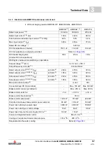
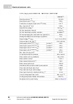
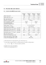
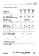
Electrical data BM553X power module
BM553
2
-
XXX
8
BM553
3
-
XXX
8
BM553
4
-
XXX
8
BM553
5
-
XXX
8
Rated input power
1)
12.0 kW
15.3 kW
23.3 kW
32.3 kW
Rated input current
1)
(I
eff
)
22.3 A
28.4 A
43.2 A
59.8 A
Max. input current (I
eff
)
44.7 A
56.8 A
86.4 A
89.7 A
Rated DC link voltage
1)
(U
DC
)
540 V
DC
DC link capacitance (internal)
820 µF
1230 µF
1640 µF
2000 µF
DC link discharging time
(internal DC link capacitance)
140 s
210 s
280 s
340 s
Output voltage
1)2)
(U
AC
)
3 x 0 V to 3 x 370 V
Output frequency at 4 kHz
8)
0 Hz to 450 Hz
Rated output current
1)4)5)6)9)
(I
AC
)
at 4 kHz
3)
22.5 A
30.0 A
45.0 A
60.0 A
Rated output current
1)4)5)6)9)
(I
AC
)
at 8 kHz
3)
18.0 A
24.0 A
36.0 A
48.0 A
Output peak current
1)4)5)7)9)
(I
AC
)
at 4 kHz
3)
45.0 A
60.0 A
90.0 A
90.0 A
Output peak current
1)4)5)7)9)
(I
AC
)
at 8 kHz
3)
36.0 A
48.0 A
72.0 A
72.0 A
Max. peak current period
7)
60 s
Power loss referring to the power input
250 W
318 W
490 W
685 W
Power input referring to the control voltage
58 W
Current of the integrated brake control
Max. 1.0 A
1)
All rated values refer to a DC link voltage of 540 V
DC
and a control voltage of 24 V.
2)
The output voltage is a pulsed DC voltage. The operating range refers to the RMS of the fundamental wave.
U
AC
3 0 V to
3
U
DC
2
-----------
10 V
–
=
without overmodulation of the PWM.
3)
Switching frequency of the inverter (adjustable).
4)
RMS at an environmental temperature of 40 °C.
Summary of Contents for b maXX 5500
Page 315: ......


