Barnes thermoplay TH-M6 User Manual Download Page 65


65 

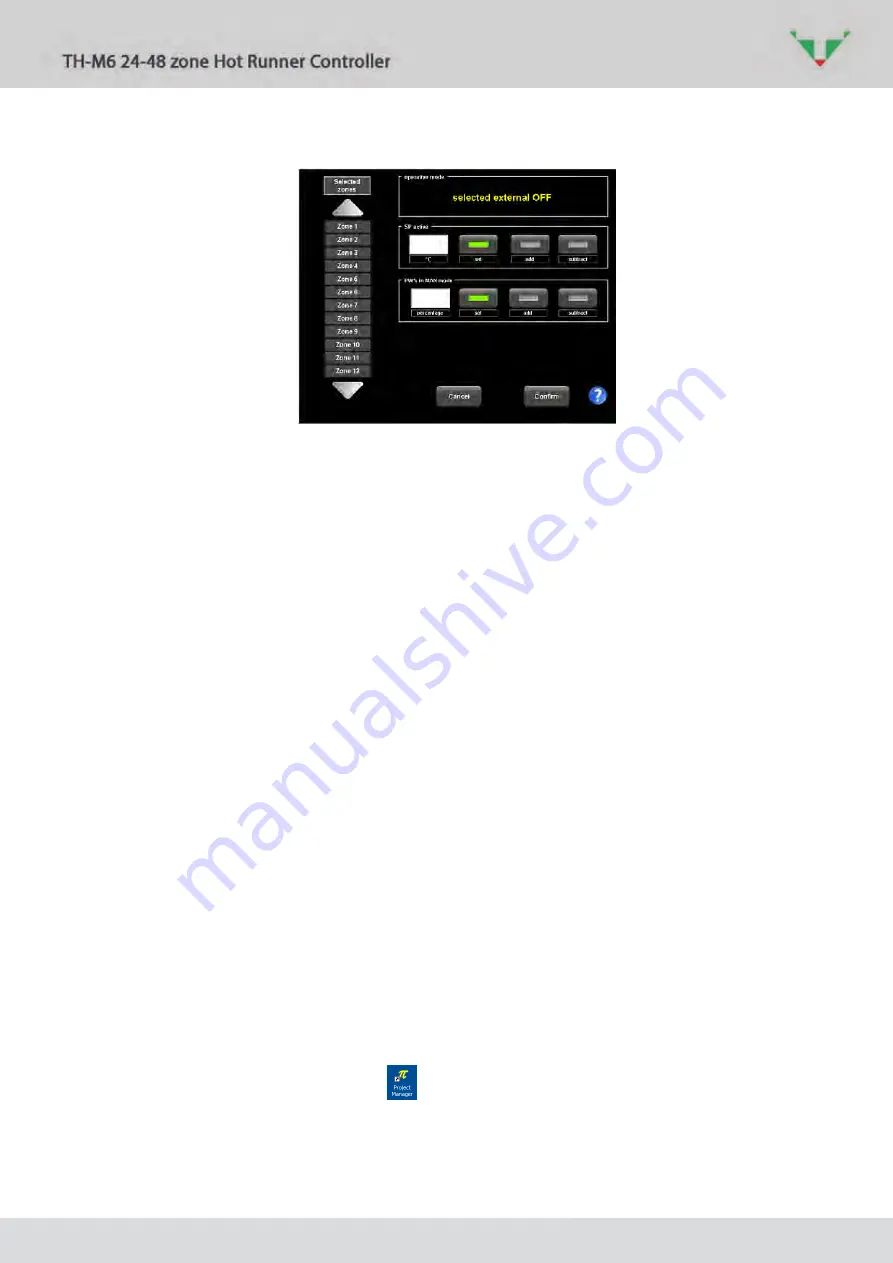
It will not be possible to change the operative mode (status) of any selected zones: 


Figure 88 

 
If any digital inputs is active, are reported also in the alarm pages. 


The digital outputs (from the temperature controller to the exterior) are: 


OUT-1

: all the temperatures are in tolerance  and there is not any alarm active.  The 

parameter for the commutation no-nc is “OUTPUT 1 (enabling signal) logical level” Idx 18 

(refer to paragraph  6.14).  The zones in “OFF”, “MAN”, “SLAVE” or “CHECK” mode are not 
considered. 


OUT-2

: emergency due to a high temperature or to a serious problem: missing phase, 

damaged SSR, interrupted heater, fuse and TC failure. Fuse and thermocouple are masked 

at the start-up: will be signalled only if not present in the initial phase.  The parameter for 

the commutation no-nc is “OUTPUT 2 (alarm signal) logical level” Idx 19 (refer to paragraph 

6.14). 


9


Supervisory software update 

If any update for supervisory software is available, follow this procedure. Copy the .zip update 

file in a USB memory stick.  

   Note: The temperature controllers with software release preceding version 2.07.40 project 

3.07 firmware 3.3, are not provided with the additional features included in revision 02.  
In order to upgrade these controllers it is required to update the software and replace 
the hardware. The new software rev.2.0 is compatible with previous hardware, but the 
new features are not  operative.  

Close the supervisory software (paragraph 6.3.2). 

Export the historical data and alarms, if you need those (refer to paragraph 6.16.2 and  6.17). 

Save the current recipe (refer to paragraph 6.11.1). 

Close the supervisory software (refer to paragraph 6.3.2). 

Start “Project Manager” with the icon 

. Then “Project”, Import”. 


Summary of Contents for thermoplay TH-M6

Page 1: ......

Page 2: ......

Page 3: ...T users management 15 6 3 main environment and selection options 17 6 3 1 Heating start and stop START STOP 17 6 3 2 TH M6 supervisory software exit 19 6 3 3 Terminal and controller shut off 20 6 3 4...

Page 4: ...e 3 3 Password added to access to Windows by closing TH M6 available only for Thermoplay user In the start up options the Service command has been added to enter in Team Viewer Options added to alarms...

Page 5: ...5 Figure 1...

Page 6: ...unction of the number of zones 4 8 power boards are present All the boards are connected to the HMI This interface allows all the operator procedure as well as the temperature and alarms supervision o...

Page 7: ...ot be considered responsible for any damages sustained resulting from improper erroneous and or unreasonable use The electrical safety of this apparatus is assured only when connected to an effective...

Page 8: ...esidual voltage to a low value On the three phases delta without neutral system supply there always be phase voltage on the heaters when main switch is in ON position Furthermore the SSR may fail in c...

Page 9: ...al Wi LAN Optional Ethernet LAN 4 Working details The apparatus is designed to regulate in the best manner the power supplied in each zone so that the temperature reaches and maintains in time the val...

Page 10: ...Drying time Idx 11 at a reduced voltage common parameter Drying voltage Idx 12 This allows the elimination of the humidity present without forming dangerous electrical discharges towards ground Phase...

Page 11: ...art Idx 6 In the status area appears SOFT In case of brief interruption soft start is automatically deactivated it is sufficient that the temperature of one zone is superior to the level of inhibition...

Page 12: ...dated in time to the two heaters 4 9 Plastic leakage alarm In case plastic material leaks the power absorption of the heater increases substantially The temperature controller finds this increment in...

Page 13: ...te 2 Plug power and thermocouples cable both in the mould and controller side 3 Turn ON the controller 4 Wait for the complete start of the terminal Normally the supervisory software automatically sta...

Page 14: ...d change hardware settings and identification label of each zone Refer to paragraph 6 18 Table 4 right side bar login logout Login and logout functions Refer to paragraph 0 logs Event log page Refer t...

Page 15: ...able 6 Table 6 default users User name Access level Password Not allowed actions No user all the functions are inhibited it s not possible to turn off the system User User 1234 zone parameters change...

Page 16: ...s are displayed If one user is selected button deletes it The button allows to create a new user and to specify what will be the relative access level Figure 8 new user creation After login was made t...

Page 17: ...f the controller is equipped with a number of zones bigger than 50 scrolling buttons on the right side bar are enabled 6 3 1 Heating start and stop START STOP In Figure 9 is showed the page that is di...

Page 18: ...11 Refer to paragraph 4 1and 4 2 for all the details dealing with Drying and Mould change functions Press the button Figure 11 heating start options If the Drying option was selected the page of Figu...

Page 19: ...TOP mode Figure 14 6 3 2 TH M6 supervisory software exit Referring to Figure 10 select option to get access to the normal Windows environment Confirm Figure 15 Figure 15 This operation is possible onl...

Page 20: ...the terminal Confirm Figure 16 Figure 16 Now you can turn OFF the whole controller main switch 3 6 3 4 Technical service through remote access Referring to Fig 10 select the option to start the remot...

Page 21: ...lta e Idx 22 BarGraph Delta The current temperature is lower than Set Point more that the set tolerance zone parameter Idx 22 BarGraph Delta The current temperature is higher than Set Point more that...

Page 22: ...ne or more zones contemporary even if the controller is in STOP mode Click anywhere in the virtual instrument to select the zone When selected it become yellow rimmed Not selected zone Selected zone F...

Page 23: ...es of the controller use the button that alternately make the function of clean the current selection and of select all When at least one zone is selected it s possible to change the regulating parame...

Page 24: ...e zone is in manual mode If one of the two blanks is selected a touch screen keyboard will appear Press the enter button to make active the typed value Figure 25 Press the confirmation button Figure 2...

Page 25: ...table page is an alternative more compact to main page Selection of one ore more zones and parameters change is possible in the same way explained for the main environment paragraph 6 3 Figure 27 tabl...

Page 26: ...if only one zone is selected in main or table environment and allow to know all the available information Select the zone than press the button the page of Figure 28 will appear Figure 28 details abou...

Page 27: ...reasing and decreasing zone parameters Ramp up GR Idx 21 e Ramp DN GR Idx 22 When the zone is in SLAVE mode the active power will be the same of the set refer to paragraph 4 8 The is the active power...

Page 28: ...g to Figure 13 button show that SP2 is the active Set Point Press the button to switch after confirmation to SP1 Figure 32 6 7 undo function This function undo the last setting action that was made as...

Page 29: ...heating power set to the value If after a time of current temperature is increased of at least test result is positive Then the test routine is recursively performed on all the selected zone Figure 3...

Page 30: ...ct this zone in the list of Figure 3 then press the button Advised values are Table 8 advised values Nozzle zone 25 6 2 Hot runner heater band zones 60 20 2 6 9 boost function boost function can be ac...

Page 31: ...the value stored in the zone parameter BOOST delta Idx 7 Press the button to switch back to normal Set Point Alternatively BOOST will switched off after a maximum time common parameter BOOST max durat...

Page 32: ...ompact style In the top left corner there is a preview of the whole picture A yellow square identify the part that is showed in the main area Click anywhere in the preview area to make the new centre...

Page 33: ...n Press button Figure 41 all the virtual instrument are deleted from the main area Referring to Figure 41 press the button yellow arrow to delete all the virtual instruments from the main area Figure...

Page 34: ...e available ones or import it from a USB memory stick with the button Figure 43 background picture Select the image that you want then press the button The selected picture will be listed among the av...

Page 35: ...6 how to place an instrument Referring to Figure 46 e g you can easily place the virtual instrument of zone Nozzle 1 Press the button specified by the red arrow Then click where indicated by the yello...

Page 36: ...e menu of Figure 47 In the top area is reported the name of the active recipe and the measure unit If any setting was modified after the recipe was saved last time a warning Active recipe was modified...

Page 37: ...new name and description can be input Click on an existing recipe in the below list if you want to overwrite it Confirmation is required click on button One existing recipe can be selected and exporte...

Page 38: ...l the settings zone and common parameters and synoptic configuration will be restored at the values saved in the recipe Figure 50 recipe loading Select the recipe you want to load in the below list Cl...

Page 39: ...ist of Figure 52 The name of the recipe includes the import date and time Figure 52 6 11 3 Restore the current recipe In the menu of Figure 47 if controller is in STOP mode the button allows to restor...

Page 40: ...ired Figure 54 6 12 graph environment In this page it s possible to graph the values of temperature Set Point and power versus time of some zones In main or table page select the zones of interest the...

Page 41: ...tes 1 hour 1 day and to go back and forward Click on the button to enable the multiple viewing then select up to a maximum of 10 zones in the left side list Click on the button It s possible to zoom a...

Page 42: ...the previous view 6 13 Zone parameters In main page select at least 1 zone then click on button Figure 58 Select one zone in the left side list the value of the parameters for this zone will be displ...

Page 43: ...43 Figure 59 zone parameters page 1 Figure 60 zone parameters page 2...

Page 44: ...to modify e g parameter SP MAX in Figure 622 red arrow Use the touch screen keyboard to input the new value then click on enter button Figure 62 Click on button to complete the operation All the zone...

Page 45: ...alue Default Value 0 SP1 0 C SPMIN SPMAX 140 1 SP2 0 C SPMIN SPMAX 70 2 BarGraph Delta Tolerance band if T SP 0 C 0 999 10 3 BarGraph Delta Tolerance band if T SP 0 C 0 999 10 4 AL1 threshold over tem...

Page 46: ...0 0 4 19 SP MIN Set Point minimum value 0 C 0 SPMAX 50 20 SP MAX Set Point maximum value 0 C SPMIN 999 400 21 Ramp up GR working Set Point increasing ramp 1 C min 0 99 9 100 0 Max 20 0 22 Ramp Dn GR...

Page 47: ...mon parameters Click on button to view and change the parameters that have the same value in all the zones of the controller Arrows allow to navigate among the pages Figure 64 Figure 65 common paramet...

Page 48: ...48 Figure 66 common parameters page 2 Figure 67 common parameters page 3...

Page 49: ...dify e g parameter Time for calculation of average power in Figure 69 Use the touch screen keyboard to input the new value then click on enter button Figure 69 Complete with button All the common para...

Page 50: ...Tuning temperature 0 sec 0 999 0 15 Derivative time under Auto Tuning temperature 0 sec 0 999 0 16 Temperature threshold to abort Soft Start 0 C 0 999 80 17 Digital filter for displayed temperature 1...

Page 51: ...emperature for overheat alarm 0 C 0 1000 0 41 Offset to 75 C pcb for overheat alarm 0 C 0 1000 0 42 Offset to 5 C for overheat STOP 0 C 0 1000 0 43 Disable supply phases test at the start 0 0 Test ena...

Page 52: ...e actions that were made by controller operators Specify the date of interest than confirm with button Each record consists of a description of the action the date and time and the user that was activ...

Page 53: ...ler finds an anomalous absorption Check if there is no leakage of plastic material AL R Heater failure The heater is interrupted or disconnected Check the connection between the temperature controller...

Page 54: ...n reported in the alarm list Alarm description zone label Activation date Activation time End date End time Identification label of the fuse Zone label Zone number 1 6 inside the relative board Serial...

Page 55: ...me range selection Figure 73 export to a tab delimited file 6 16 3 Active alarms Click on button to show only the active alarms Now for each record are reported all the information of Table 12 except...

Page 56: ...uration Figure 75 alarm configuration In the Alarm Configuration page Figure 77 alarm configuration settings all the alarms contained in Table 11 are shown and it is possible to set them to stand by N...

Page 57: ...nfiguration settings By pressing the button the user exit from configuration and the active alarm list is displayed 6 16 5 Alarm shout down The button visible in Figure 75 alarm configuration 6 allows...

Page 58: ...vironment Select in main or table page the zones of which you need to export historical data Then click on the button in the upper bar In the next window specify the desired time range Figure 78 Click...

Page 59: ...a The buttons and allows to change the time range and to export the data in a tab delimited file as described in paragraph 6 16 2 Referring to Figure 80 there is one record per second In Table 13 are...

Page 60: ...B Then oldest recorded data will be deleted to get fee space for the new data saving 6 18 hardware setting environment Click on the to access to hardware configuration of the controller The reported i...

Page 61: ...hange identification label and colour with the same procedure saw in paragraph 6 3 6 e g the first 16 zones in Figure 82 Then select Figure 83 Set the fields Description Number and Colour as displayed...

Page 62: ...riously damaged If it is represented in the main page as shown in Fig 18 it must be replaced It s easy to identify where the faulty zone is located in main page select one of the faulty zones then cli...

Page 63: ...ata trovata Remove the faulty fuse with the help of a screwdriver as illustrated in Figure 85 Replace the fuse with one having the same characteristics extra rapid fuse FF16A 3A 6 3 L 32 Figure 85 fus...

Page 64: ...The parameter for the switch no nc is INPUT 1 switch to SP2 logical level Idx 22 refer to paragraph 6 14 Figure 86 DIN 2 automatic commutation of all the zones in OFF message in bottom area OFF select...

Page 65: ...ameter for the commutation no nc is OUTPUT 2 alarm signal logical level Idx 19 refer to paragraph 6 14 9 Supervisory software update If any update for supervisory software is available follow this pro...

Page 66: ...t option as displayed in Figure 90 Then click on button Set the new project as the default one with button Figure 91 Close Project Manager and start supervisory software refer to paragraph 5 Login as...

Page 67: ...noptic configurations event log and historical data and alarm Then click on button to proceed Load the recipe that was active in previous project refer to paragraph 6 11 2 Now you can delete the pervi...

Page 68: ...its box indicated that at the end of the life of the product it must be gathered separately from other waste The differentiated waste disposal of such equipment must be organized and managed by the p...

Page 69: ...Germany T 49 2351 661180 info thermoplay de GREECE JOSEPH N AVATAGELOS CO 22 Skra Str 14342 N Filadelfia T 3 021 02712912 avatag tellas gr HUNGARY THERMAFER Vilci ut184 1138 Budapest T 36 1 412 0935...

Page 70: ......

Page 71: ...15 58511Liidenscheid Germany lei 49 2351 661180 info thermoplay de THERMOPLAY PORTUGAL Unipessoal Lda Rua Dr Manuel Ribeiro DeOliveira R C Esq 2400 178Leiria Portugal lei 351 244577247 geral thermopl...

Reviews: