10
Motor
- Slide lower bearing (6) and motor shaft squarely
into the seal plate (1) until bearing seats on the bottom. Place
stator over rotor, lining up motor bolts with holes in seal plate
(1). Position capacitor (21, single phase units) so that it will
lay on the opposite side of the cable entry bosses of the
motor housing (5). Reconnect capacitor leads. Torque motor
tie bolts to 17 in-lbs. Set square ring (8) in groove on seal
plate (1).
F-3.3) Wiring Connections:
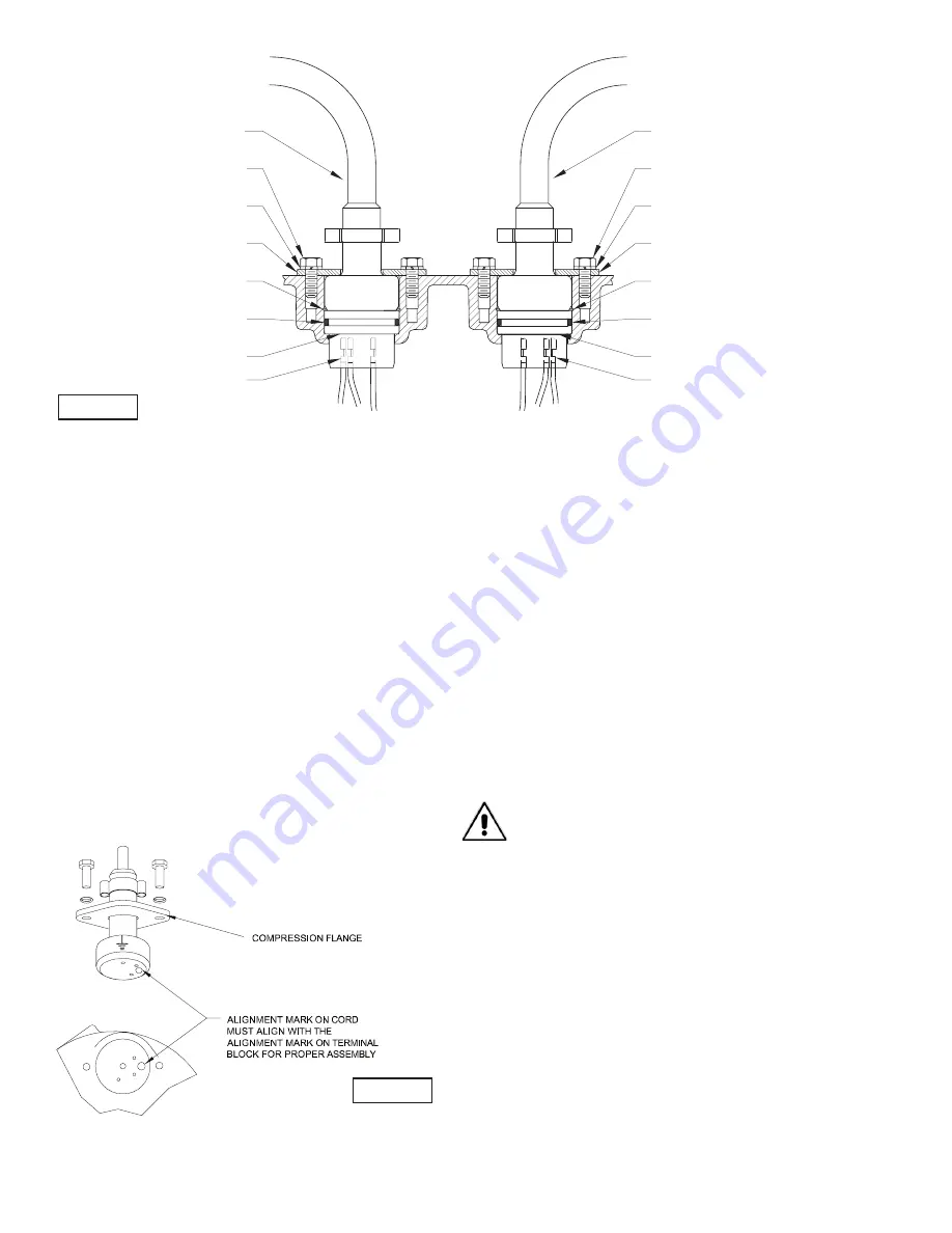
Check power cables (30) and control cable (32, if used), for
cracks or damage and replace if required (see Figure 5).
Make internal wiring connections which are independent of
the terminal block as shown in (Figure 10), using connectors
(14), terminal (15) and wire assemblies (18) as required. Do
not use wire nuts. Slip motor leads and ground wire through
fi berglass sleeve. Lower motor housing (5) down onto seal
plate (1) while aligning holes and stringing motor leads
through the cable entry bore(s). (Slipping cords inside a 1 ft.
length of .5” conduit makes this easier). Place socket head
cap screws (9) through seal plate (1) into motor housing (5)
and torque to 60 in-lbs.
Reconnect motor and optional control leads to the underside
of the terminal block(s) (23), (38 optional) as shown in Figure
5. Note that the pins are numbered underneath the terminal
block. Place o-ring (40) into groove in terminal block and
lubricate with dielectric oil. Press the terminal block (23) (38
optional) into the housing so it seats completely below the
snap ring groove. Place snap ring (41) into groove in cable
entry bore of housing. Repeat terminal block installation for
control cable, if equipped.
F-3.4) Cable Assemblies:
Power/Control Cable- Refi ll the cooling oil as outlined in
paragraph F-1.4. Make wire connections as outlined in
paragraph F-3.3. Insert female end of cable plug into housing
bore aligning timing mark with hole in terminal block (23)
(38 optional) (see Figure 6). Compress cable plug with
compression fl ange (30a)(32a) by tightening cap screws (16)
into the housing (5). Torque to 132 in-lbs.
F-4) Shaft Seal Service:
Important ! - Handle seal parts with extreme care.
DO NOT scratch or mar lapped surfaces.
F-4.1) Disassembly and Inspection:
To expose shaft seal (31) for examination disassemble volute
and impeller as outlined in paragraph F-2.1. If further repair
is required remove retaining ring (31d), spring (31c) and
rotating member (31b) from shaft (see Figure 9). Examine all
seal parts and especially contact faces. Inspect seal for signs
of wear such as uneven wear pattern on stationary members,
chips and scratches on either seal face.
FIGURE 6
FIGURE 5
POWER CORD (30)
CAP SCREW (16)
LOCKWASHER (11)
COMPRESSION FLANGE (30a)
SNAP RING (41)
O-RING (40)
TERMINAL BLOCK (23)
CONTROL CORD (32)
CAP SCREW (16)
LOCKWASHER (11)
COMPRESSION FLANGE (32a)
SNAP RING (41)
O-RING (40)
TERMINAL BLOCK (38)
TERMINAL
TERMINAL


