Barko Hydraulics BARKO LOADERS 275B SER-ERS Service Manual Download Page 66

page 66

page 66

page 66

page 66

page 66

275B SER

800-00152

INTRODUCTION

INTRODUCTION

INTRODUCTION

INTRODUCTION

INTRODUCTION

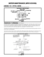
This manual is a step-by-step guide to assembly and disassembly of torque-hub units.  It is designed for the customer
or shop mechanic who is repairing a particular model of torque-hub final drive.

Users of this manual should note that each part mentioned is followed by an identification number enclosed in
parentheses.  These part numbers may be referred to in the Parts List section of this manual and on the cross-
sectional view of this unit.

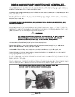
Any specialized tools normally used to assemble this unit are noted in the assembly procedures.  However, it is not
mandatory that these tools be used in this unit’s assembly.  Bearing cups and cones can be pressed using a punch
and hammer along their top edges.  Seals can be pressed by laying a board flat on top of the seal and them hammering
the board down until it meets the hub. Studs can be hammered into stud holes.  Should you use these methods,
be very careful not to damage parts when using a punch and/or hammer.

Users should familiarize themselves with the procedures for roll and leak testing and bolt tightening and torquing
found on the following two pages before getting started.
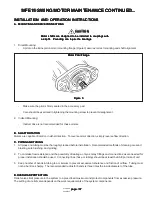
SAFETY

SAFETY

SAFETY

SAFETY

SAFETY

Standard safety practices should be followed during the disassembly and assembly procedures described.  Safety
glasses and safety shoes should be worn.  Heavy, heat resistant gloves should be used when heated components
are handled.  Be especially alert when you see the word CAUTION.  This indicates that a particular operation could
cause personal injury if not performed properly or if certain safety procedures are not followed.

ROLL AND LEAK TESTING

ROLL AND LEAK TESTING

ROLL AND LEAK TESTING

ROLL AND LEAK TESTING

ROLL AND LEAK TESTING

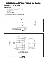
Torque-hub units should always be roll and leak tested before disassembly and after assembly to make sure that
the unit’s gears and sealants are working properly.  The following information briefly outlines what to look for when
performing these tests.

THE ROLL TEST

THE ROLL TEST

THE ROLL TEST

THE ROLL TEST

THE ROLL TEST
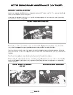
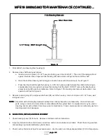
The purpose of a roll test is to determine if the unit’s gears are rotating freely and properly.  You should be able to
rotate the gears in your unit by applying a constant force to the roll checker.  If you feel more drag in the gears only
at certain points, then the gears are not rolling freely and should be examined for proper installation or defects.  Some
gear packages roll with more difficulty than others.  Do not be concerned if the gears in your unit seem to roll hard
as long as they roll with consistency.

THE LEAK TEST

THE LEAK TEST

THE LEAK TEST

THE LEAK TEST

THE LEAK TEST
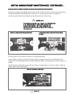
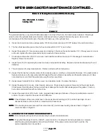
The purpose of a leak test is to make sure the unit is air tight. You can tell if your unit has a leak if the pressure gauge
reading on your air checker starts to fall once the unit has been pressurized.  Leaks will most likely occur at the main
seal or wherever o-rings or gaskets are located.  The exact location of a leak can usually be detected by brushing
a soap and water solution around the main seal and where o-rings or gaskets meet the exterior of the unit then
checking for air bubbles.  If a leak is detected in a seal, o-ring, or gasket, the part must be replaced.

TIGHTENING AND TORQUING BOLTS

TIGHTENING AND TORQUING BOLTS

TIGHTENING AND TORQUING BOLTS

TIGHTENING AND TORQUING BOLTS

TIGHTENING AND TORQUING BOLTS

If an air impact wrench is used to tighten bolts, extreme care should be taken to insure that the bolts are not tightened
beyond their indicated torque specification.  Never use an impact wrench to tighten should bolts; all shoulder bolts
should be tightened by hand.

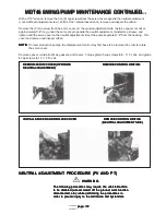
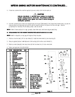
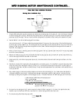
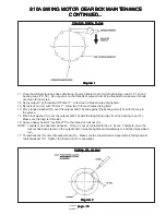
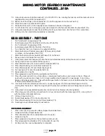
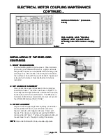
The following steps describe the proper procedure for tightening and torquing bolts or socket head cap screws in a
bolt circle.

1. Tighten (but do not torque) bolt “A” until snug.
2. Go to the opposite side of the bolt circle and tighten bolt “B” until equally snug.
3. Continue around the bolt circle and tighten the remaining bolts.

SWING MOTOR GEARBOX MAINTENANCE (S10A)

SWING MOTOR GEARBOX MAINTENANCE (S10A)

SWING MOTOR GEARBOX MAINTENANCE (S10A)

SWING MOTOR GEARBOX MAINTENANCE (S10A)

SWING MOTOR GEARBOX MAINTENANCE (S10A)

Summary of Contents for BARKO LOADERS 275B SER-ERS

Page 1: ...nary Electric Remote with Electric Remote Station Stationary Electric Remote with Electric Remote Station Stationary Electric Remote with Electric Remote Station Stationary Electric Remote with Electr...

Page 2: ...Hydraulic System B Hydraulic System B Hydraulic System B Hydraulic System 23 23 23 23 23 Hydraulic Schematics 24 Hydraulic Pressure Settings 25 Hydraulic Reservoir Maintenance 26 Hydraulic Oil Filter...

Page 3: ...page 3 page 3 page 3 page 3 page 3 275BSER 800 00152 Introduction Introduction Introduction Introduction Introduction...

Page 4: ...industrial accidents each year A professional operator should also be familiar with the information contained in other applicable sources such as American National Standards SAE OSHA etc ADDITIONALINF...

Page 5: ...ition Ignition Key Switch Key Switch Key Switch Key Switch Key Switch Power On Power On Power On Power On Power On Accessory Accessory Accessory Accessory Accessory Power Off Power Off Power Off Power...

Page 6: ...evels render each and all Barko warranties null and void and constitute an obvious misuse and abuse of our product WARNING WARNING WARNING WARNING WARNING MODEL 275B MODEL 275B MODEL 275B MODEL 275B M...

Page 7: ...BARKO within ten 10 days from the date on which the defect was discovered and any claim submitted within thirty 30 days after repair work is completed BARKO warranty does not cover 1 Defects damage o...

Page 8: ...e lowered to When machine is not operating or when leaving cab boom and attachment must be lowered to When machine is not operating or when leaving cab boom and attachment must be lowered to When mach...

Page 9: ...re leaving cab If necessary to work engine before leaving cab If necessary to work on machine with lifted boom securely support on machine with lifted boom securely support on machine with lifted boom...

Page 10: ...m such precautions to protect personnel from such precautions to protect personnel from such precautions to protect personnel from such precautions to protect personnel from such injury Personnel shou...

Page 11: ...Always be pump or engine is not operating Always be pump or engine is not operating Always be certain that boom and attachment are properly certain that boom and attachment are properly certain that b...

Page 12: ...gainst human skin Serious compressed air against human skin Serious compressed air against human skin Serious compressed air against human skin Serious compressed air against human skin Serious injury...

Page 13: ...in any way attachment so that they cannot move or fall in any way attachment so that they cannot move or fall in any way attachment so that they cannot move or fall in any way Stick Boom Stick Boom S...

Page 14: ...Always clean fluid spills Clean the machine and disconnect power before doing any welding Cover rubber hoses and other flammable parts Never ground arc welder or electrical accessories through turnta...

Page 15: ...00152 Maintenance Maintenance Maintenance Maintenance Maintenance A PREVENTIVE MAINTENANCE A PREVENTIVE MAINTENANCE A PREVENTIVE MAINTENANCE A PREVENTIVE MAINTENANCE A PREVENTIVE MAINTENANCE Maintena...

Page 16: ...and may cause structural damage void the warranty and may cause structural damage void the warranty and may cause structural damage void the warranty and may cause structural damage void the warranty...

Page 17: ...lways needed for Safety glasses or goggles are always needed for Safety glasses or goggles are always needed for eye protection from electric arcs from shorts or eye protection from electric arcs from...

Page 18: ...rol Lever Linkage if applicable Lubricate Bolts Nuts Bolts Nuts Bolts Nuts Bolts Nuts Bolts Nuts Check for proper torque every 50 hours Retorque if necessary Hydraulic Collector Hydraulic Collector Hy...

Page 19: ...a daily basis 10 10 10 10 10 WARNING WARNING WARNING WARNING WARNING Boom is shown in lifted operating position Always shut down the machine and lower Boom is shown in lifted operating position Alway...

Page 20: ...ety goggles visible Use a piece of cardboard or wood to find leaks but do not use bare hand Wear safety goggles visible Use a piece of cardboard or wood to find leaks but do not use bare hand Wear saf...

Page 21: ...x Mounting Bolts 310 Ft Lbs Turntable Bearing Bolts 310 Ft Lbs Grapple Bearing Bolts continuous rotation grapples only 127 Ft Lbs Grapple Motor Mounting Bolts 64 Ft Lbs WARNING WARNING WARNING WARNING...

Page 22: ...ON HEAD GRADE 9 HEAD GRADE 9 HEAD GRADE 9 HEAD GRADE 9 HEAD GRADE 9 BOW MALLOY BOW MALLOY BOW MALLOY BOW MALLOY BOW MALLOY RECOMMENDED RECOMMENDED RECOMMENDED RECOMMENDED RECOMMENDED TORQUEFOOT TORQU...

Page 23: ...3 page 23 page 23 page 23 page 23 275BSER 800 00152 Maintenance Maintenance Maintenance Maintenance Maintenance B HYDRAULIC SYSTEM B HYDRAULIC SYSTEM B HYDRAULIC SYSTEM B HYDRAULIC SYSTEM B HYDRAULIC...

Page 24: ...page 24 page 24 page 24 page 24 page 24 275BSER 800 00152 HYDRAULIC SCHEMATICS HYDRAULIC SCHEMATICS HYDRAULIC SCHEMATICS HYDRAULIC SCHEMATICS HYDRAULIC SCHEMATICS...

Page 25: ...tings on a new machine will void Altering the settings on a new machine will void the warranty the warranty the warranty the warranty the warranty The following is a list of pressure settings used on...

Page 26: ...es and out of tubelines and openings openings openings openings openings CAUTION CAUTION CAUTION CAUTION CAUTION Figure 1 Figure 1 Figure 1 Figure 1 Figure 1 Check oil level in reservoir before each p...

Page 27: ...TOP VIEW OF RESERVOIR TOP VIEW OF RESERVOIR Figure 2 Figure 2 Figure 2 Figure 2 Figure 2 INSPECTION INSPECTION INSPECTION INSPECTION INSPECTION COVER COVER COVER COVER COVER FILLER CAP FILLER CAP FIL...

Page 28: ...e Filters do not function when elements are clogged with contaminant to the point of bypass Therefore it its important to do three things 1 Check the Filter Indicator frequently to determine when the...

Page 29: ...wl Screw filter bowl with element inside to filter head CAUTION CAUTION CAUTION CAUTION CAUTION These filter elements are not re usable These filter elements are not re usable These filter elements ar...

Page 30: ...mospheric pressure air may be drawn in where fluid will not necessarily leak out 5 Fluid level too low This can cause vortexing at pump inlet in reservoir thus drawing in air 6 Air trapped in filter w...

Page 31: ...ings keep dirt out of tubelines and openings keep dirt out of tubelines and openings keep dirt out of tubelines and openings PIPE THREAD SEALER PIPE THREAD SEALER PIPE THREAD SEALER PIPE THREAD SEALER...

Page 32: ...item 8 Heating item 10 7 and the stiff portion of 1 in a 200 oven for 5 minutes will make it more pliable Some kits may contain extra seals When installing the wear rings items 2 6 put the cuts on opp...

Page 33: ...1 1 10 10 10 10 10 MODULAR BACKUP RING MODULAR BACKUP RING MODULAR BACKUP RING MODULAR BACKUP RING MODULAR BACKUP RING 1 1 1 1 1 11 11 11 11 11 O RING O RING O RING O RING O RING 1 1 1 1 1 1 1 1 1 1 3...

Page 34: ...be lost after machine engine is shut down Operating without accumulators properly installed can shut down Operating without accumulators properly installed can shut down Operating without accumulators...

Page 35: ...manual on collector parts list Port numbers are stamped into collector for easy reference HYDRAULIC COLLECTOR SEAL KIT INSTRUCTIONS HYDRAULIC COLLECTOR SEAL KIT INSTRUCTIONS HYDRAULIC COLLECTOR SEAL...

Page 36: ...m properly for installation Heat teflon rings to 200 400 degrees Fahrenheit WARNING WARNING WARNING WARNING WARNING Do not heat teflon rings beyond 400 degrees Fahrenheit Do not heat teflon rings beyo...

Page 37: ...hould be followed very closely to ensure that the valve bank is properly reassembled after repairs have been made See Figure 1 Figure 1 Figure 1 Figure 1 Figure 1 Figure 1 A Take a waterproof quick dr...

Page 38: ...s to be serviced Next poppet sleeve Item 17 Figure 3 4 unless it is to be serviced Next poppet sleeve Item 17 Figure 3 4 unless it is to be serviced Next poppet sleeve Item 17 Figure 3 4 unless it is...

Page 39: ...y to avoid damage Place the spool in a soft jawed vise and remove the stripper bolt Item 14 with a wrench Cautious application of heat may be required to free the stripper bolt because an anaerobic th...

Page 40: ...Component Parts See Figure 3 4 4 Back Cap Screw 2 5 Back Cap 1 6 RetainerPlate 3 7 Backup Ring 2 8 Spool Seal 2 9 Retainer Plate Screw 2 10 Check Valve Cap 1 Or Valve Cap F I N 1 11 O RingSeal 1 12 Ch...

Page 41: ...he valve housing extends across the o ring face of the valve housing extends across the o ring face of the valve housing extends across the o ring face of the valve housing It should not be stoned or...

Page 42: ...ure prepare parts properly may result in assembly failure prepare parts properly may result in assembly failure prepare parts properly may result in assembly failure Then lightly coat the detent balls...

Page 43: ...80 90 ft lbs ITEM ITEM ITEM ITEM ITEM DESCRIPTION DESCRIPTION DESCRIPTION DESCRIPTION DESCRIPTION QTY QTY QTY QTY QTY 1 O RING 2 2 O RING 1 3 BACKUPRING 1 4 GASKET WASHER 1 Figure 5 Figure 5 Figure 5...

Page 44: ...pplied to the threads Use heat carefully to avoid warpingspool PREPARATION OF PARTS PREPARATION OF PARTS PREPARATION OF PARTS PREPARATION OF PARTS PREPARATION OF PARTS 1 Clean adhesive from threads of...

Page 45: ...to insert seals Seals are similar in size Be sure to insert seals 1 10 in their proper position They are not 1 10 in their proper position They are not 1 10 in their proper position They are not 1 10...

Page 46: ...No motion slow or erratic system operation Wornpump Defective cylinder or motor Low reservoir oil level Clogged suction strainer Suction line restricted Relief valve not properly set Relief valve pop...

Page 47: ...ced without major disassembly of the unit However replacement of the shaft seal requires removal of the pump or motor from the machine 1 Remove the retaining ring from the housing 2 Carefully remove t...

Page 48: ...embly may change the setting and cause erratic Disassembly may change the setting and cause erratic Disassembly may change the setting and cause erratic Disassembly may change the setting and cause er...

Page 49: ...of neutral which will necessitate readjustment result in the loss of neutral which will necessitate readjustment result in the loss of neutral which will necessitate readjustment result in the loss o...

Page 50: ...ontrol linkage disconnected from the handle the control may be incorrectly adjusted CHECK HIGH PRESSURE RELIEF VALVES CHECK HIGH PRESSURE RELIEF VALVES CHECK HIGH PRESSURE RELIEF VALVES CHECK HIGH PRE...

Page 51: ...stem is sluggish or will not operate in either direction inspect the orifice For pumps with serial number 02 XX XX XXXXX or below remove the hex plug using a 9 16 wrench and remove the orifice with an...

Page 52: ...he ground work function to be disabled wheels raised off the ground work function to be disabled wheels raised off the ground work function to be disabled wheels raised off the ground work function di...

Page 53: ...r clockwise until the other system pressure start to increase Turn the servo adjustment screw clockwise half the amount of rotation noted above While holding the servo adjustment screw from turning to...

Page 54: ...disconnected etc while performing the function disconnected etc while performing the procedure in order to prevent injury to the technician procedure in order to prevent injury to the technician proce...

Page 55: ...unction disconnected etc while performing the raised off the ground work function disconnected etc while performing the raised off the ground work function disconnected etc while performing the proced...

Page 56: ...istons reverse and fluid is pushed out of the cylinder block into the outlet kidney slot Inline Piston Motor Operation Inline Piston Motor Operation Inline Piston Motor Operation Inline Piston Motor O...

Page 57: ...3 Figure 3 Figure 3 Make sure the pilot is firmly seated in the accessory pad Care should be exercised in tightening the mounting screw to prevent misalignment 2 IndirectMounting Indirect drive is not...

Page 58: ...wrench with short extension and sockets 0 1inch micrometer Feelergauge Internal Truarc pliers In addition an arbor press is needed to service bearings SPECIAL TOOLS Special tools are shown in Figures...

Page 59: ...icle if it is on a slope The piston motor cannot act as a parking brake as a parking brake as a parking brake as a parking brake as a parking brake CAUTION CAUTION CAUTION CAUTION CAUTION Before break...

Page 60: ...in a clean area The presence of dirt and system Always work in a clean area The presence of dirt and system Always work in a clean area The presence of dirt and system Always work in a clean area The...

Page 61: ...lve Block Removal of Race from Blind Hole of Valve Block Removal of Race from Blind Hole of Valve Block Removal of Race from Blind Hole of Valve Block 5 Remove rotating group parts 9 through 18 as a u...

Page 62: ...a short piece of 1 1 2 heavy wall tubing as a tool NOTE NOTE NOTE NOTE NOTE All parts must be thoroughly cleaned and kept clean during inspection and assembly Clean all removed parts using a commercia...

Page 63: ...lace if defective 12 Inspect housing 3 for cracks cross threads and wear Check snap ring groove for wear and the proper depth Check gasket mounting face for deep scratches or damage that could cause l...

Page 64: ...f tapered roller bearing must face out of the housing 6 Install valve block 2 to housing 3 without gasket 4 and rotating group Turn shaft 21 to seat the bearings then torque the valve block attaching...

Page 65: ...toward valve block 2 18 Install two housing pins 19 and place a new gasket 4 over them Cover the unit and set aside for final assembly F F F F F FINAL ASSEMBLY OF PISTON MOTOR FINAL ASSEMBLY OF PISTO...

Page 66: ...on briefly outlines what to look for when performing these tests THE ROLL TEST THE ROLL TEST THE ROLL TEST THE ROLL TEST THE ROLL TEST The purpose of a roll test is to determine if the unit s gears ar...

Page 67: ...PIPE PLUG 1N 2 MAGNETIC PIPE PLUG 2 1 INTERNALGEAR 3 1 CARRIER ASSEMBLY 3A 1 CARRIER 3B 3 ROLLPIN 3C 6 BEARINGCUP 3D 6 BEARINGCONE ITEM ITEM ITEM ITEM ITEM QTY QTY QTY QTY QTY DESCRIPTION DESCRIPTION...

Page 68: ...nput gear 13 6 Remove thrust washer 15 7 Remove thrust bearing 16 8 Remove thrust washer 15 9 Remove o ring 5 from the counterbore around rim of hub 1G 10 Remove pipe plug 1L from hub 1G 11 Remove int...

Page 69: ...his step Safety glasses should be worn during this step Safety glasses should be worn during this step 10 Drive the roll pin 3B into its hole in carrier 3A Use a punch to drive roll pin flush to carri...

Page 70: ...t get oil on the threads of output shaft Wipe threads to make sure threads are clean for next step 12 Spray output 1A threads with Primer T Allow two to three minutes drying time 13 Spray lock nut 1J...

Page 71: ...n contact 10 Spray a light coat of oil inside internal gear 2 11 Place thrust washer 15 onto shoulder of output shaft 1A 12 Place thrust bearing 16 onto thrust washer 15 13 Place thrust washer 15 over...

Page 72: ...NDING HERE Diagram 3 Diagram 3 Diagram 3 Diagram 3 Diagram 3 MAIN ASSEMBLY PART TWO MAIN ASSEMBLY PART TWO MAIN ASSEMBLY PART TWO MAIN ASSEMBLY PART TWO MAIN ASSEMBLY PART TWO 1 Using hoist place cove...

Page 73: ...then it should be rolled 70 times in both directions 11 Leak test the unit at a pressure of 8 P S I for 2 3 minutes 12 At this point the main assembly is complete FILLINGWITHOILANDOILCHANGE FILLINGWIT...

Page 74: ...age 74 page 74 page 74 page 74 275BSER 800 00152 Maintenance Maintenance Maintenance Maintenance Maintenance C ELECTRICAL SYSTEM C ELECTRICAL SYSTEM C ELECTRICAL SYSTEM C ELECTRICAL SYSTEM C ELECTRICA...

Page 75: ...properly installed before unit is energized 7 7 7 7 7 Keep hands hair clothing and tools away from all moving parts when operating or repairing equipment Keep hands hair clothing and tools away from a...

Page 76: ...onditions overload relays provide protection btween 110 and 120 of their current rating No extra allowance for service factor is necessary On across the line starting the trip time for properly sized...

Page 77: ...ON CAUTION Make sure both lube plugs have been inserted after lubricating Make sure both lube plugs have been inserted after lubricating Make sure both lube plugs have been inserted after lubricating...

Page 78: ...minimum and maximum measurements must not exceed the ANGULAR limit specified in Table 1 3 OFFSET ALIGNMENT 3 OFFSET ALIGNMENT 3 OFFSET ALIGNMENT 3 OFFSET ALIGNMENT 3 OFFSET ALIGNMENT Align so that a...

Page 79: ...sition seals on hubs to line up with grooves in cover Position gaskets on flange of lower cover half and assemble covers so that the match marks are on the same side see Figures 6 and 7 If shafts are...

Page 80: ...page 80 page 80 page 80 page 80 page 80 275BSER 800 00152 Trouble Shooting Trouble Shooting Trouble Shooting Trouble Shooting Trouble Shooting...

Page 81: ...BLEM CAUSE CAUSE CAUSE CAUSE CAUSE WindshieldWiper Washer if applicable does not work Wiper Washerswitchneeds service Wiper or washer motor needs service Disconnectedordamagedwiring Replace switch Rep...

Page 82: ...rty Relief valve improperly adjusted Incorrect hydraulic oil viscosity Excessive load Pump not receiving hydraulic oil Damagedline Any or all of the following Replace dirty filters Clogged inlet line...

Page 83: ...MACHINE OPERATIONS TROUBLE SHOOTING MACHINE OPERATIONS TROUBLE SHOOTING MACHINE OPERATIONS TROUBLE SHOOTING MACHINE OPERATIONS TROUBLE SHOOTING MACHINE OPERATIONS TROUBLE SHOOTING Boom will not remain...

Page 84: ...se damaged WARNING WARNING WARNING WARNING WARNING Do not reproduce any decals listed or shown here for Do not reproduce any decals listed or shown here for Do not reproduce any decals listed or shown...

Page 85: ...als not used on this machine Base Kit decals not used on this machine Base Kit decals not used on this machine Base Kit decals not used on this machine Base Kit decals not used on this machine are ite...

Reviews: