page 64
page 64
page 64
page 64
page 64
275B SER
800-00152
MFE19 SWING MOTOR MAINTENANCE CONTINUED...
MFE19 SWING MOTOR MAINTENANCE CONTINUED...
MFE19 SWING MOTOR MAINTENANCE CONTINUED...
MFE19 SWING MOTOR MAINTENANCE CONTINUED...
MFE19 SWING MOTOR MAINTENANCE CONTINUED...
Figure 13
Figure 13
Figure 13
Figure 13
Figure 13
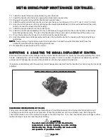
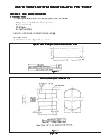
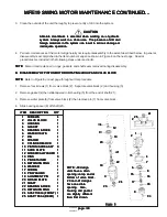
1. If the shaft bearing (22) requires replacement, install a new bearing race into housing (3). Use tool shown in Figure 6
to press bearing grace in place. Make sure the bearing race is oriented properly to accept the roller bearing before
pressing into the housing. The race must be bottomed against the shoulder of the housing at completion of press.
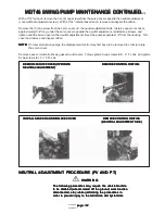
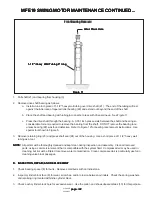
2. Install shaft (21) into front shaft bearing (22) as follows:
Use a short piece of 1-1/2" heavy wall tubing (approximately 6" long) over the drive spline of the shaft (tubing ends
must be square within 0.005 inch). The tubing must be long enough to make contact with the inner race of the front
bearing. Press the shaft through the bearing with an arbor press until the bearing bottoms against the shoulder of
the shaft. See Figure 14.
3. Remove the short piece of tubing and turn shaft bearing (22) in it's race with the end of the shaft. The bearing rollers
must turn free and smooth.
4. Obtain a shaft bearing spacer kit and install the thickest bearing spacer (8) over shaft (21) with the chamfer facing
into the housing (toward the shoulder on the shaft).
5. Slide bearing (5) on shaft and up against spacer (8). Small diameter of tapered roller bearing must face out of the
housing.
6. Install valve block (2) to housing (3) without gasket (4) and rotating group. Turn shaft (21) to seat the bearings then
torque the valve block attaching screws (1) to five Lb. In. Retorque screws while turning shaft. The bearings are
seated when shaft does not free up while turning. Check the opening between the valve block and housing to be as
even as possible.
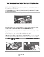
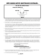
7. Use a feeler gauge to measure opening between valve block (2) and housing (3). Four measurements should be
obtained equidistant around unit. A tapered feeler gauge is especially useful for this purpose. Average the four
readings by adding them together and dividing by four (4). Calculate thickness of shaft bearing spacer as follows.
0.140 0.001
Required bearing spacer thickness to
provide 0.002 0.001 inch preload.
+
++
+
+-----
+
++
+
+-----
+
++
+
+-----
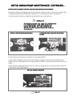
8. Remove four mounting screw (1) and remove valve block (2) from housing (3). If unit is a through shaft model,
install a new rear shaft seal (25) into valve block (2). Garter spring will face into the motor.
9. Remove bearing (5) and bearing spacer (8).
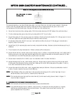
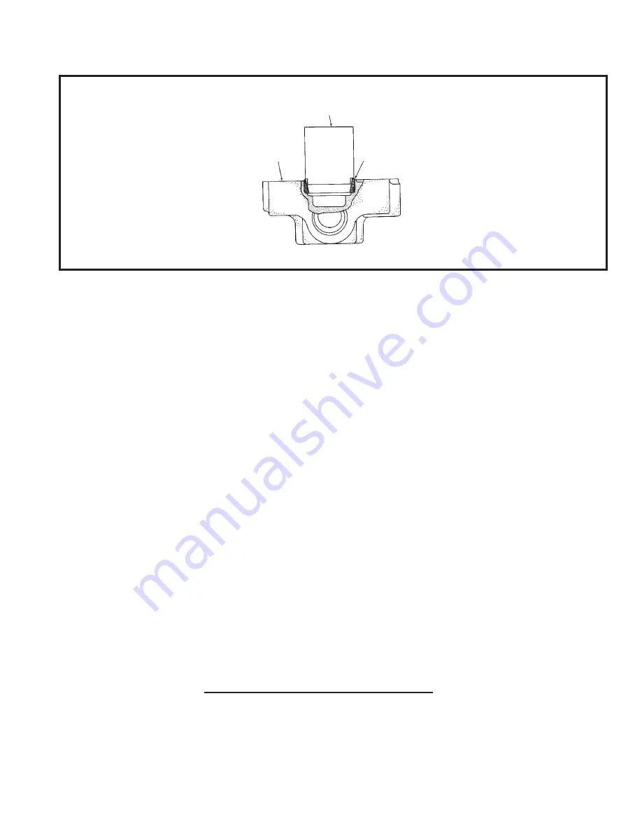
Valve Block Race Installation Procedure
Valve Block Race Installation Procedure
Valve Block Race Installation Procedure
Valve Block Race Installation Procedure
Valve Block Race Installation Procedure
Bearing Race Installation Tool
Bearing Race Installation Tool
Bearing Race Installation Tool
Bearing Race Installation Tool
Bearing Race Installation Tool
Valve Block
Valve Block
Valve Block
Valve Block
Valve Block
Bearing Race
Bearing Race
Bearing Race
Bearing Race
Bearing Race
+0.150 Measured thickness of bearing spacer
-0.027 Average gap
+0.002 0.001 Preload setting
+0.015 Compressed thickness of gasket

