background image

Manual 2100-628 

Page 

12 of 24

WIRING – MAIN POWER

Refer to the unit rating plate for wire sizing information 
and maximum fuse or circuit breaker size.  Each 
outdoor unit is marked with a “Minimum Circuit 
Ampacity”.  This means that the field wiring used must 
be sized to carry that amount of current. Depending 
on the installed KW of electric heat, there may be 
two field power circuits required.  If this is the case, 
the unit serial plate will so indicate.  All models are 
suitable only for connection with copper wire. Each 
unit and/or wiring diagram will be marked “Use Copper 
Conductors Only”.  These instructions 

must be 

adhered 

to.  Refer to the National Electrical Code (NEC) for 
complete current carrying capacity data on the various 
insulation grades of wiring material.  All wiring must 
conform to NEC and all local codes.

The electrical data lists fuse and wire sizes (75° C 
copper) for all models including the most commonly 
used heater sizes.  Also shown are the number of field 
power circuits required for the various models with 
heaters.

The unit rating plate lists a “Maximum Time Delay 
Relay Fuse” or circuit breaker that is to be used with 
the equipment.  The correct size must be used for 
proper circuit protection and also to assure that there 
will be no nuisance tripping due to the momentary high 
starting current of the compressor motor.

The disconnect access door on this unit may be locked 
to prevent unauthorized access to the disconnect.  To 
convert for the locking capability, bend the tab located 
in the bottom left-hand corner of the disconnect 
opening under the disconnect access panel straight 
out.  This tab will now line up with the slot in the door.  
When shut, a padlock may be placed through the hole 
in the tab preventing entry.

See “Start Up” section (page 17) for important 
information on three phase scroll compressor start ups.

See Table 6 on page 23 for Electrical Specifications.

WIRING – LOW VOLTAGE WIRING 

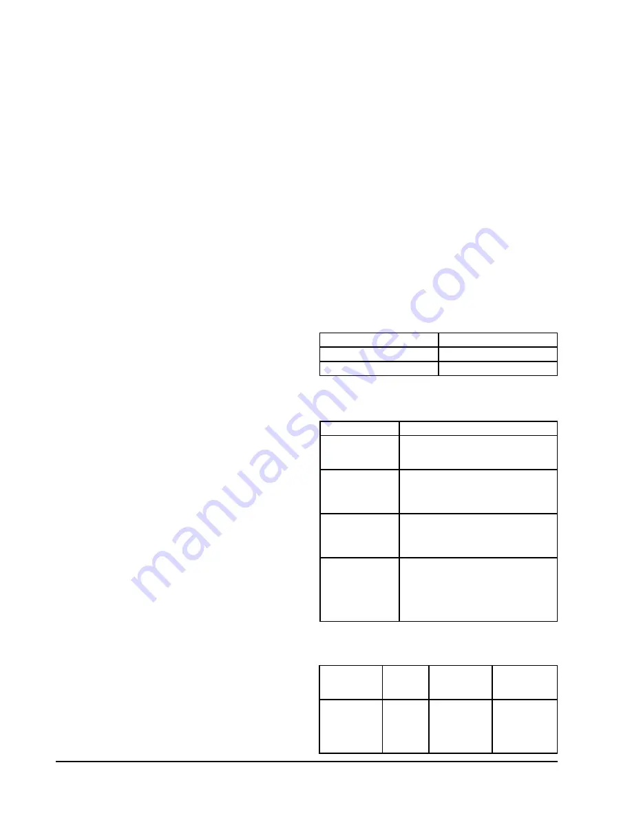
All 230/208V 1 phase equipment has dual primary 
voltage transformers.  All equipment leaves the factory 
wired on 240V tap.  For 208V operation, reconnect 
from 240V to 208V tap.  The acceptable operating 
voltage range for the 240 and 208V taps are:


TAP RANGE


240 

253 – 216


208 

220 – 187

NOTE:  The voltage should be measured at the field 

power connection point in the unit and while 

the unit is operating at full load (maximum 

amperage operating condition).

18 guage copper, color-coded thermostat cable is 
recommended.  See Figure 7 on page 14 for thermostat 
connections.

Low Voltage Connection

These units use a 24-volt AC low voltage circuit.  
The “

RT

” terminal is the 24V transformer output, 

and the “

R

” terminal is the 24VAC 

hot

 terminal for 

the operation of the equipment.  “

RT

” and “

R

” are 

connected with brass jumper bar which can be removed 
and “

RT

” and “

R

” connected to external NC (normally 

closed) contact such as a fire/smoke detector that will 
cause immediate shutdown of the equipment upon 
activation.

C

” terminal is


grounded

.

G

” terminal is the 

fan input

.

Y

” terminal is the 

compressor input for cooling 

W1

” terminal is the 

1st stage electric heat

.

TABLE 3

THERMOSTAT WIRE SIZE

Transformer

VA

FLA

Wire Gauge

Maximum 

Distance  

(Feet)

55

2.3

20 gauge
18 gauge
16 gauge
14 gauge
12 gauge

45
60

100
160
250

TABLE 1

LOW VOLTAGE CONNECTIONS 

FOR DDC CONTROL

Fan Only

Energize G

Cooling Mode

Energize Y, G

Heating Mode

Energize W1, G

Part Number

Predominate Features

8403-057

(TH3110D1040)

1 stage Cool, 1 stage Heat
Electronic Non-Programmable
Auto or Manual changeover

8403-058

(TH5220D1151)

2 stage Cool, 2 stage Heat
Electronic Non-Programmable
HP or Conventional (Default: HP)
Auto or Manual changeover

8403-059

(TH5220D1219/U)

2 stage Cool, 2 stage Heat
Electronic Non-Programmable
HP or Conventional (Default: AC)
Auto or Manual changeover

8403-060

(1120-445)

3 stage Cool; 3 stage Heat
Programmable/Non-Programmable 
Electronic
HP or Conventional
Auto or Manual changeover
Dehumidification Output

TABLE 2

WALL THERMOSTAT

Summary of Contents for K36A2-A

Page 1: ...6A2 A K36A2 N K42A2 A K42A2 N K48A2 A K48A2 N INSTALLATION INSTRUCTIONS Bard Manufacturing Company Inc Bryan Ohio 43506 www bardhvac com Manual 2100 628 Supersedes NEW Date 12 1 14 K60A2 A K60A2 N K36...

Page 2: ...able 8 Indoor Blower Performance 24 Table 9 Maximum ESP Electric Heat Only 24 Table 10 Electric Heat 24 Getting Other Information and Publications 3 Wall Mount General Information 4 Wall Mount Model N...

Page 3: ...er and Summer Air Conditioning Duct Design for Residential ACCA Manual D Winter and Summer Air Conditioning and Equipment Selection FOR MORE INFORMATION CONTACT THESE PUBLISHERS ACCA Air Conditioning...

Page 4: ...e entire air conditioning system should be carefully read before beginning the installation Note particularly Starting Procedure and any tags and or labels attached to the equipment While these instru...

Page 5: ...s Ducts through the walls must be insulated and all joints taped or sealed to prevent air or moisture entering the wall cavity Some installations may not require any return air duct A metallic return...

Page 6: ...which secure the unit to the outside wall surface at both sides A bottom mounting bracket attached to skid for shipping is provided for ease of installation but is not required 2 The unit itself is su...

Page 7: ...BLE PANEL ACCESS HEATER ELECTRICAL ENTRANCE HIGH VOLTAGE ENTRANCE ELECTRIC HEAT ACCESS PANEL DISCONNECT C BREAKER BUILT IN RAIN HOOD 4 PITCH J K H C I A 2 13 D 3 4 I D DRAIN HOSE Mounting Brackets Loc...

Page 8: ...4 1 1 4 29 3 4 32 12 5 1 2 2 NOTES WALL STRUCTURE 1 SUPPLY AIR IT IS RECOMMENDED THAT A BEAD OF OPENING Right Side View RAIN FLASHING SILICONE CAULKING BE PLACED BEHIND RECOMMENDED 1 CLEARANCE FROM T...

Page 9: ...mbustible materials This is required for the first 3 feet of ducting It is important to insure that the 1 4 inch minimum spacing is maintained at all points Failure to do this could result in overheat...

Page 10: ...TURN AIR SUPPLY AIR FACTORY SUPPLIED RAIN FLASHING SUPPLY AIR MIS 548 A SIDE VIEW I A C K E 1 000 B 1 000 SUPPLY DUCT OVER FRAME INTERIOR FINISHED WALL ALL AROUND DUCT FRAMING MATERIAL EXTERIOR FINISH...

Page 11: ...ALL OPENING W GRILLE SUPPLY DUCT MAYBE LOCATED IN AN ATTIC OR BELOW CEILING RAFTERS AS SHOWN CEILING RAIN RETURN AIR SLEEVE WALL SUPPLY AIR DUCT RAFTERS RAFTERS RETURN AIR OPENING W GRILLE RAIN FALSE...

Page 12: ...on page 23 for Electrical Specifications WIRING LOW VOLTAGE WIRING All 230 208V 1 phase equipment has dual primary voltage transformers All equipment leaves the factory wired on 240V tap For 208V oper...

Page 13: ...mid Operation Light will come on and the lag unit compresser and blower will operate until the set point of humidty controller is satisfied or cancelled by a call for cooling b If the space temperatur...

Page 14: ...Manual 2100 628 Page 14 of 24 FIGURE 7 THERMOSTAT CONNECTIONS...

Page 15: ...TDOWN NC CONTACTS OPEN ON ALARM Rt REMOVE JUMPER FOR COMP DISABLE FEATURE 2 REMOVE JUMPER WHEN CONNECTING GEN CONTACT 3 REMOVE JUMPER WHEN CONNECTING FIRE SHUTDOWN CONTACT 1 NC CONTACTS OPEN ON ALARM...

Page 16: ...ple leaks and recharges R 410A refrigerant is close to being an azeotropic blend it behaves like a pure compound or single component refrigerant The remaining refrigerant charge in the system may be u...

Page 17: ...run in reverse rotation for an extended period of time the compressor s internal protector will trip All three phase compressors are wired identically internally As a result once the correct phasing i...

Page 18: ...m relay circuit will energize Recycling the wall thermostat resets the manual lockout Low Pressure Switch Bypass and Lockout Sequence If the low pressure switch opens for more than 120 seconds the com...

Page 19: ...e unit to the serial plate charge REMOVAL OF FAN SHROUD 1 Disconnect all power to the unit 2 Remove the screws holding both grilles one on each side of unit and remove grilles 3 Remove screws holding...

Page 20: ...URE 10 MOTOR HIGH VOLTAGE CONNECTIONS FIGURE 10 NOTE Bard Models PA13242 PA13302 PA13362 A B PA13422 A B C PA13482 A B C PA13602 A B C contain the X13 Series Motors TROUBLESHOOTING GE X13 SERIES ECM2...

Page 21: ...e common and the appropriate motor terminal 1 5 G input is typically on terminal 1 but refer to wiring diagram a If the low voltage communication is not present check the demand from the thermostat Al...

Page 22: ...ser Fan Operation page 17 Model Return Air Temperature C Pressure 35 37 39 41 43 45 47 49 51 53 55 K36 2 27 DB 19 WB Low Side High Side 143 145 147 148 150 152 154 156 158 160 162 368 388 408 429 449...

Page 23: ...gle Circuit Minimum Circuit Ampacity Maximum External Fuse or Ckt Brkr Field Power Wire Size Ground Wire K36L2 A0Z 208 230 60 1 1 A05 1 K36L2 N0Z 400 60 3 1 8 2 10 14 14 N05 1 9 8 15 14 14 K42L2 A0Z 2...

Page 24: ...Amps BTUH 5 20 8 17 065 18 1 12 800 6 9 0 21 330 TABLE 7 RECOMMENDED AIRFLOW Model Nominal Rated CFM Nominal Rated ESP Recommended Airflow Range K36A K36L 1100 15 930 1350 K42A K42L 1300 20 1485 1070...

Reviews: