background image

74    Barco - RHDM-1701 - User manual   

Full functionality description

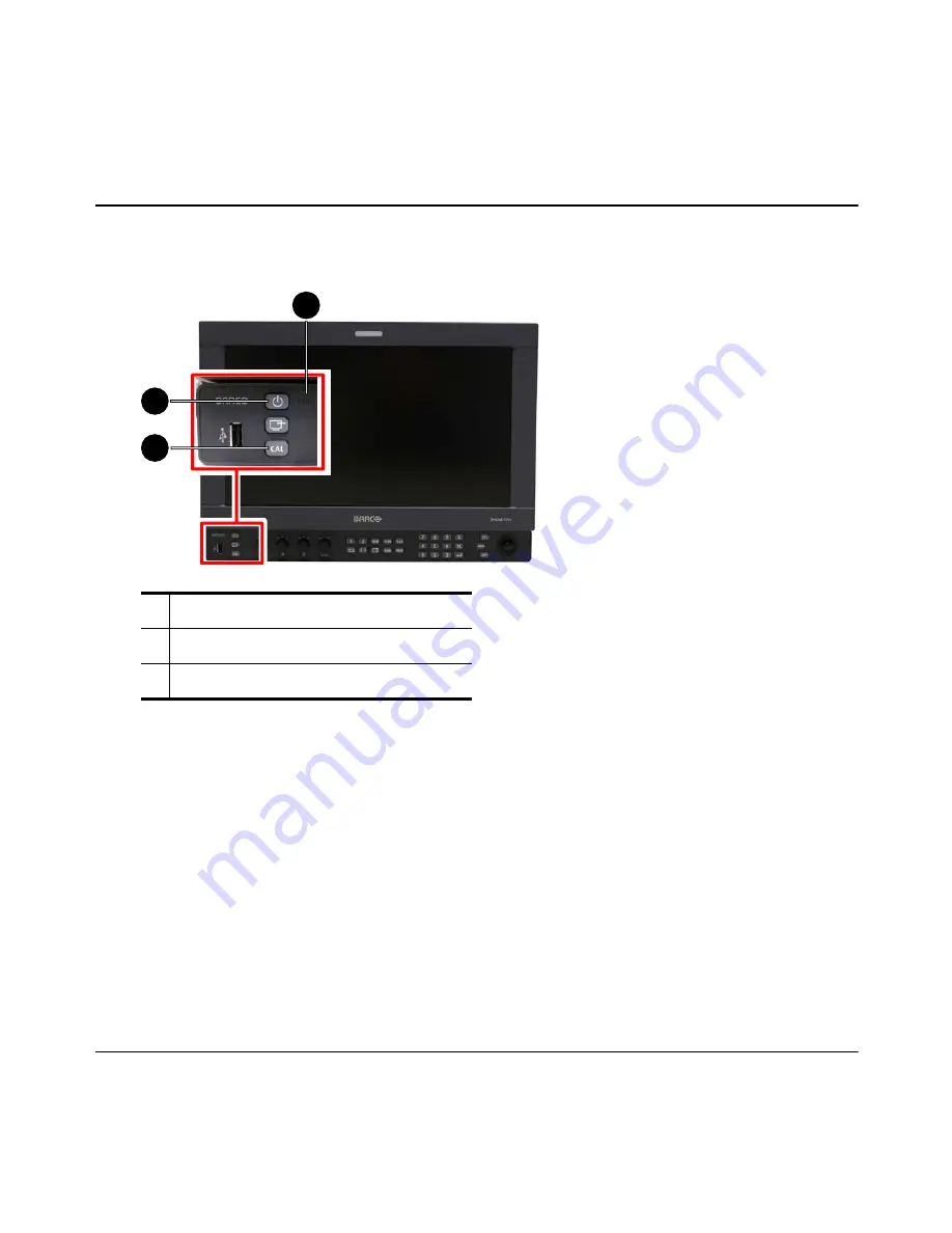
4.1.3  Indicator lights

 Figure 21: Location of indicator lights

The indicator lights give information about the status of the display unit.
Standby/Power LED:

•  Orange: The display unit is in soft standby. All signals at the input boards are processed. The

backlights and panel are turned off.

•  Green: The display unit is powered. All signals at the input boards are processed.
•  LED is not lit: The display is in hard standby or the power connector is disconnected.

Fault LED:

•  Red: A Fault has occurred.

1

Standby/Power LED (green or orange)

2

Fault  LED  (red)

3

Calibration LED (orange)

1

2

3

Summary of Contents for RHDM-1701

Page 1: ...RHDM 1701 16 5 LCD Broadcast Monitor User manual K5960051 01 ...

Page 2: ...2 Barco RHDM 1701 User manual Intentionally left blank ...

Page 3: ...stomer notice Thank you for buying Barco Barco is a world leader in display and visualization solutions We are convinced that you will enjoy our products 1 2 Change record Revision Date Description 00 April 2010 Initial release 01 July 2010 Update for software V3 04 ...

Page 4: ...o is made for the most frequent operations the user would like to execute It will help the user to solve the question quickly since it is built up as a non chronological guide Basic knowledge of the display unit expert question The chapter full functionality description contains all there is to know about the display unit The information is ordered in a chronological way Technical details Check th...

Page 5: ...gy used in this manual is explained in detail in this chapter This allows the beginner and the expert to fall back on a consistent naming convention used throughout this manual Chapter 7 Addendum The Addendum is quite extensive and includes the more technical parts of information that are useful for system integrators and people who want to know more about the technical specifications of the displ...

Page 6: ...the feature level the color accuracy and stability with time and temperature perfect grey scale representation deep and correct blacks motion handling with scanning backlights and a myriad of other features give large benefits to professionals active in these markets The Key features of the display unit are LCD panel 16 5 41 9cm diagonal 1920x1080 10 bit panel Typical contrast 1000 1 Barco guarant...

Page 7: ...cuit for LED stabilization with temperature Embedded spectrometer for overall color stabilization over time Embedded special sensors for LED uniformity and color stabilization over time Modular input configuration 4 slots Slot 1 1 SDI input board standard Slot 2 1 SDI input board optional Slot 3 future option DVI Slot 4 future option DVI SDI module specifications Possible inputs 2 x SDSDI 2 x HDSD...

Page 8: ...lected Depending on the feature pack addi tional options can be available Broadcast RHDM 1701 B standard feature pack Accepts SD and HD SDI timings 2 inputs with loop through outputs Selectable color space EBU SMPTE C Rec 709 and Native color temperature and gamma Configurable aspect ratio and safe area markers Standard controls picture background saturation hue color channel selection mono chrome...

Page 9: ...and should be respected throughout the manual WARNING Warnings presented in this manual provide information which if not adhered to may result in personal injury or death CAUTION Cautions presented in this manual provide information which if not adhered to may result in damage to the equipment NOTE Notes presented in this manual provide information which emphasize points significant to understand ...

Page 10: ... Federal Communication Commission FCC notice This equipment has been tested and found to comply with the limits of an FCC class refer to the technical specifications of the specific unit for more details about the corresponding class These limits are designed to provide reasonable protection against harmful interference when the equipment is operated in a commercial environment This equipment gene...

Page 11: ...utside of the specification Any failures resulting from an accident negligence such as but not limited to removing or delet ing system files licensed software product files misuse circuit failure or any change damage due to fire water thunder or lightning power failure or fluctuation disruption of communication lines or due to force majeure or any reason foreign to the equipment Any specific servi...

Page 12: ...oid dissemination of toxic substances in the environment and to diminish the pressure on natural resources we encourage you to use the appropriate take back systems Those systems will reuse or recycle most of the materials of your end of life equipment in a sound way The crossed out wheeled bin symbol invites you to use those systems If you need more information about the collection reuse and recy...

Page 13: ...e technical specifications Always power down the unit before disconnecting the power cable Unplug the display unit from the power source when not in use IMPORTANT Immediately unplug if the power supply cord is damaged the unit has been dropped or the cabinet is damaged the unit does not operate normally by following the operation instructions WARNING Do not remove the cover without authorization R...

Page 14: ...es are visible on the screen below the pressing object e g finger the pressure is already too high and the LCD may already break under these circumstances Do not hit the LCD screen with hard objects Do not rub the LCD screen with rough materials Do not touch the LCD screen with hard materials Hard materials can cause scratches on the sur face of the LCD screen Examples of hard material are fingern...

Page 15: ... break If any part of the skin or body comes in direct contact with the liquid immediately wash the affected areas with plenty of water for at least 15 minutes If any symptoms are present after washing get medical care 1 7 8 Specific handling precautions Do not power the unit with other input sources as specified in the technical specifications AC power source 90 264 Vac 47 63 Hz Do not push objec...

Page 16: ...fer to The quick installation sheet The section Installation in the Addendum 2 2 Overview locations for operation Figure 1 Overview of operational controls indicators and OSD functionalities Different operation interfaces 1 Status bar 2 OSD menu 3 Toolbox 4 Under Monitor Display bar Picture Adjustment bar 5 Control panel 6 Indicator lights 5 6 1 3 2 4 ...

Page 17: ...formation on each part and each function of the display unit Figure 2 Overview indicator lights NOTE The display unit has a certain delay time between powering up and displaying an image on the screen 20 seconds The delay time originates from several internal checks and calibrations that are performed to guarantee the correct display of the image When in doubt about the status of the display unit ...

Page 18: ...ndby Power LED green Display unit is switched on no further actions are necessary Standby Power LED orange Display unit is switched on soft standby the panel and backlights are switched off Press on the control panel to activate the panel and backlights Standby Power LED white Display unit is switched off hard standby press on the control panel to switch the display unit on The Standby Power LED w...

Page 19: ...t for the product flavor you have purchased B or P If you have purchased any optional feature packs there are also envelopes with license information for each feature pack The product the license sheets for the basic flavor B or P and any additional license sheet all have their own unique pincodes that have to be registered on our website before activating your product Overview of the basic steps ...

Page 20: ... First operation If the grace period has expired you will see the Welcome message with instructions on the screen Write down the pincode of the display unit that is displayed on the screen you will need to register it on the website ...

Page 21: ...s and licenses by entering their pincodes on the personalized webpage to obtain license files for your products https my barco com productregistration In case my barco com is not available please contact Barco service see contact info mentioned in the above screenshot 4 Download the license file from the product registration website and upload it to your product using a USB key ...

Page 22: ... already have an existing my barco com account please click Login and enter your exist ing user name and password to proceed with the login Otherwise if you are a new customer please sign up to open a my barco com account This step is done only once Register at my barco com display PINcode Registered monitor USB License PINcode license file ...

Page 23: ...Barco RHDM 1701 User manual 23 First operation The welcome screen appears Click on the left tab Register Pincodes ...

Page 24: ...rco RHDM 1701 User manual First operation 5 Register Pincodes Add all pincodes of the new products and licenses to be registered When adding codes the pincode appears in the list at the bottom of the window ...

Page 25: ...ucts will open with a list of all entered pincodes at the top 6 Assign licenses to products In the middle of the Show Products page you have the possibility to assign a license feature pack to the monitor of your choice Select the license you would like to assign to that monitor and click Add Feature Pack ...

Page 26: ...here is an overview of the assigned licenses at the bottom of the page 7 Get License File If you agree with this assignation click on Get License File Following page with a link appears Click the link here and save the file on location of your choice ...

Page 27: ...Plug the USB stick in each monitor that has been registered and wait 1 2s until it becomes activated The display unit will recognize the license file automatically The following message appears when the update is successful The display unit should function immediately IMPORTANT Important note Only license files with a filename barcoLicense case sensitive no extensions will be recognized by the RHD...

Page 28: ...ed 9 Troubleshooting If the registration process produces an error check if the license codes were entered correctly If the problem persists contact Barco You might by mistake assign the wrong license to a monitor with a particular S N e g a moni tor that is installed at a certain position This can be corrected First upload the wrong license file to the monitor Generate a new pincode via the monit...

Page 29: ...the main menu Press Menu to open the OSD menu Provide the administrator password Administrator password is 313329 Click on Generate new Pincode in the License OSD menu IMPORTANT Important note Do not generate a new pincode unless you plan to install new licenses on your product Generating a new pincode will disable the feature packs on your product ...

Page 30: ...30 Barco RHDM 1701 User manual First operation License OSD menu Confirming this dialog will remove all feature packs from the display unit and generate a new pincode ...

Page 31: ...display unit With the newly generated pincode you can assign new other licenses to the product on the Barco website https my barco com productregistration Generate a new license file Place the license file on a USB stick and connect the USB stick to all display units that need to be updated with the new licenses The following message appears when the update is successful and the display unit will ...

Page 32: ...erent sections of buttons and knobs that allow the user to interact with the display unit in a fast and easy way Buttons Some of the buttons especially the functions keys have a double functionality and can be used as follows The function keys contain most of the settings of the display unit It is important to understand the division of the function keys based on the effect that they have on the p...

Page 33: ...windows that can be selected by pressing for window 1 and for window 2 Once a window is se lected pressing the same button will toggle between the inputs that are available for that window 2 View mode Enables the user to select the way the windows should be viewed on the screen e g only window 1 only window 2 or both windows shown next to each other 3 Display settings These settings have an effect...

Page 34: ...input signal settings and the setting of the display unit The line highlighted in white indicates the active window Calibrated settings The display unit is a calibrated instrument that continuously monitors several parameters to ensure correct representation of colors and luminance levels The user can decide to run the display unit in a non calibrated mode by adjusting the settings defined by the ...

Page 35: ...e used to display the image on the screen This setting is a geographic region preference set ting Enter the color working space toolbox by pressing long press Set the required white point default D65 Store the setting under a Custom preset Enter the input window menu by pressing or long press Set the signal input range to be visualized on the screen default 64 1019 Select the OETF opto electric tr...

Page 36: ...ge the license installed on the display unit Activate the Admin mode that you can find in the main menu Press to open the OSD menu Provide the administrator password Short press Instantaneous effect Long press press longer than 2 seconds Open a toolbox with advanced settings ...

Page 37: ...not generate a new pincode unless you plan to install new licenses on your product Generating a new pincode will disable the license and the feature packs on your product When you have generated a new pincode by acci dent follow the instructions below to reinstall the license and the feature packs on the display unit Figure 8 License OSD menu ...

Page 38: ...nd generate a new pincode The following message is shown on the screen if generate new pincode is confirmed It is recommended to deactivate the admin mode after removing the feature packs from the display unit With the newly generated pincode you can assign new other licenses to the product on the Barco website https my barco com ...

Page 39: ...le on my barco com Place the license file on a USB stick and connect the USB stick to all display units that need to be updated with the new licenses The following message appears when the update is successful and the display unit will operate normally immediately ...

Page 40: ...utput connectors when the display unit is in hard standby Up to 2 inputs can be applied to the SDI board simultaneously In the table below the possible combinations are shown To select a valid signal open the input selection toolbox by pressing long on the button of the window in which the input signal has to be shown or The concept of selection and viewing of the valid signals is summarized in th...

Page 41: ... above window 1 is active and shows the signal applied to input 1 on the screen Pressing will toggle between the available inputs input 1 and input 2 Pressing will select window 2 When window 2 is active its selected input in this example this would be input 2 is shown on the screen NOTE When no valid input is present for a certain input option the screen will blank and show the Invalid input icon...

Page 42: ...utomatically after the timeout time set in the OSD settings menu in the OSD menu Figure 11 Zoom in of the status bar at the top of the screen NOTE Input settings are connected to the window When input settings are changed for a specific window they are stored instantaneously 3 4 How to change the color working space Figure 12 Location of buttons to change color working space Press to cycle through...

Page 43: ...s to both windows The color working space which is currently used to display the image on the screen is shown in the status bar 3 5 How to visualize the dark levels The dark levels are accessible with the background control on the image adjustments knobs The background control can be changed between 127 and 128 and is set to 0 by default The unit of the values of the background control is expresse...

Page 44: ...44 Barco RHDM 1701 User manual How to Video signal LCD drive Black 0 White 100 Black offset clipping bright levels 100 clipping dark levels Visualize super bright Visualize super dark ...

Page 45: ...he OSD menu by pressing Move with the trackball to select the Input settings in the main menu Press or or move with the trackball to the right to open the Input settings menu Move with the trackball down to the Black correction setting of the appropriate window When black correction is set at a value different from 0 press or to select the value move with the trackball down or type 0 on the numeri...

Page 46: ...l In some cases the correctness of the colors at the dark grey levels are of higher importance than the contrast The black correction in the Input settings OSD menu can be set for each window separately To optimize the color correctness of the dark grey levels the black correction should be set to 100 As a tradeoff for the optimized color correctness of the dark grey levels the contrast is reduced...

Page 47: ... mode setting of the appropriate window Press or to select the mode Move with the trackball up or down to select black line insertion mode Press or to confirm the black line insertion mode 3 9 How to change the aspect ratio Figure 14 Location of the button to change the aspect ratio Press to toggle between all possible aspect ratios The aspect ratio is applied instanta neously to the window or Pre...

Page 48: ...t the color channel Press Select Channel selection Move with the trackball to highlight Channel selection Press or to activate the Channel selection option The setting is applied immediately to the selected window Select the color channel Move with the trackball to highlight a color channel Press or to select a color channel The setting is applied immediately to the selected window Track ball ...

Page 49: ...mmediately to the selected window NOTE The color channel selection toolbox shows the selected color channel for the active window only When only one color channel is selected the cal err indicator light will light up orange to alert the user the display unit is working out of the calibrated range 3 11 How to show two input signals next to each other Press Figure 16 View mode functionality SINGLE I...

Page 50: ... to pan the image and to zoom in on the image These functions can be performed for window 1 and window 2 separately To change the relative size of the two parts of the screen in the Pan Zoom mode Move with the pointer to the separating line in the middle of the screen using the trackball When the double arrow appears while hovering with the pointer above the separating line press continuously and ...

Page 51: ... 1 and window 2 are shown next to each other Move the pointer using the trackball to the window where the video signal has to be panned Press continuously to grab the image and use the track ball to pan the image When is released the pointer can be moved to pan the other window or to perform a new pan on the same window Pointer can be used for panning Track ball ...

Page 52: ... Move the magnifying glass using the trackball to the location where the video signal has to be zoomed in Press continuously to lock the place and use the trackball to zoom in out When is released the magnifying glass can be moved to another window or another spot on the screen IMPORTANT When an image is zoomed pixel repetition is used to display the image on the screen This means that the image i...

Page 53: ...rom one RHDM monitor to another via USB 3 14 2 Restoring the active preset A short press on the calibration button loads restores the current active preset Use case example Suppose preset 1 was loaded and is thus the current active preset A user changes on purpose or by accident some of the critical user settings As a result the CAL button will light up orange to indicate this As explained in the ...

Page 54: ...Presets Go to the OSD menu by pressing Move with the trackball to select the Presets in the main menu Press or or move with the trackball to the right to open the Presets menu Move with the trackball to Load Store or Erase depending on the desired action and press or to open the submenu ...

Page 55: ...d can be changed optionally and the preset can be stored Via web interface page Preset management Select Preset management from the selection menu on the left hand side of the webpage Go to Preset to load to load either the factory preset or one of the 5 user presets Go to Store Current Settings as to store the current settings to one of the 5 user presets Go to Preset to remove to remove a select...

Page 56: ...56 Barco RHDM 1701 User manual How to ...

Page 57: ...preset 2 name The name of the preset as shown in the Load Store submenu or when defining the name in the Store submenu Example So preset 1 with name Test 1 will be represented by a file with name 1 Test 1 pre 3 14 5 Transferring presets over USB Via OSD User presets created on one RHDM monitor can be transferred to another monitor by using an USB stick Upon plugging in an USB stick a popup menu wi...

Page 58: ...f the USB stick has presets in the root of the USB stick The presets are represented as files on the root of the USB stick and must be named 1 pre 5 pre representing presets 1 5 If for example the USB stick contains two preset files in its root 1 name1 pre and 4 some_name pre then by invoking this option presets 1 and 4 on the display will be replaced by those on the USB stick Note that installing...

Page 59: ...ction Via web interface page Preset management Select Preset management from the selection menu on the left hand side of the webpage Go to Download presets to download presets from the monitor into your PC Go to Preset to upload to upload a preset file from your PC to the monitor ...

Page 60: ...60 Barco RHDM 1701 User manual How to ...

Page 61: ...nded target medium This color consistency is achieved by using color gamut mapping A practical way of gamut mapping is to use look up tables that transform a given signal value to a new value The used tool for gamut mapping is a three dimensional look up table 3D LUT Currently the monitor supports three types of user 3D LUT files Truelight Cinespace and Autodesk A user 3D LUT file can be uploaded ...

Page 62: ...nu or via the web interface 3 15 3 3D LUT upload via web interface Connect the display unit to the local network Plug an ethernet cable in ethernet port 0 or ethernet port 1 Connect with the pc to the display unit Check the IP address that is assigned to the ethernet port Press to open the Dis play Information toolbox Write down the IP address of the corresponding ethernet port Open a browser wind...

Page 63: ...n menu on the left hand side of the webpage Click on Upload file to go to the Upload Custom 3D LUT page Browse for a User 3D LUT file by clicking on the Browse button Note that the file can have any name and doesn t have to be name 3d lut Hit the upload button to upload the file to the monitor ...

Page 64: ...e Input settings menu Move with the trackball down to User 3D LUT and press or to open the sub menu Check the box Enable by pressing or to activate the 3D LUT file that was loaded in the display unit Via web interface page User 3D LUT Select User 3D LUT from the selection menu on the left hand side of the webpage Check LUT active on window 1 to activate the 3D LUT file on window 1 Check LUT active...

Page 65: ...second order digits e g from 1 00 to 1 01 IMPORTANT It is not possible to downgrade the software version of the display unit with a major software revision 3 16 2 Software upload via ethernet 1 Connect the display unit to the local network Plug an ethernet cable in ethernet port 0 or ethernet port 1 2 Connect with the pc to the display unit Check the IP address that is assigned to the ethernet por...

Page 66: ...66 Barco RHDM 1701 User manual How to Open a browser window and type in the Address bar http the IP address e g http 150 158 200 140 The web interface of the display unit will open ...

Page 67: ...Barco RHDM 1701 User manual 67 How to 3 The software upload Select Admin from the selection menu on the left hand side of the webpage ...

Page 68: ...How to An authentification will be requested To enter the Admin section User name admin Password admin117234 When the valid user name and password are entered the Admin section will be opened in the webpage Click on Upgrade firmware ...

Page 69: ... the progress of the software upload while the display unit will show the following warning message on the screen After the software upload the display unit will reboot automatically and will start up using the newly uploaded software IMPORTANT If the upload of the new software would fail or would be interrupted the display unit will reboot into the failsafe mode The software version of the failsa...

Page 70: ... the display unit at the back of the display unit The display unit will search for the latest software upload file The following warning window appears on the screen The display unit will automatically start the software upload after 10 seconds unless the display unit is powered off or the USB stick is removed When the display unit is busy with the upload of the new software the following warning ...

Page 71: ... software version of the failsafe mode is the most recent software version that was uploaded success fully NOTE It is advisable to remove the USB stick after software update since the display unit will automatically recognize the firmware on the USB stick at each power up or activation from hard standby The display unit will then start the automated firmware update process This does not happen aft...

Page 72: ... Figure 19 Overview of operational controls indicators and OSD functionalities Different operation interfaces 1 Status bar 2 OSD menu 3 Toolbox 4 Under Monitor Display bar Picture Adjustment bar 5 Control panel 6 Indicator lights 4 1 2 Operational mode overview The operational status of the display unit can be summarized in the figure below 5 6 1 3 2 4 ...

Page 73: ...Barco RHDM 1701 User manual 73 Full functionality description Figure 20 Operational mode overview ...

Page 74: ...LED Orange The display unit is in soft standby All signals at the input boards are processed The backlights and panel are turned off Green The display unit is powered All signals at the input boards are processed LED is not lit The display is in hard standby or the power connector is disconnected Fault LED Red A Fault has occurred 1 Standby Power LED green or orange 2 Fault LED red 3 Calibration L...

Page 75: ... Figure 22 Drawing of the control panel The control panel allows the user to change a wide variety of settings in a clear and easy way To apply the desired settings the control panel is equipped with a USB port press buttons press and rotary knobs a trackball 4 1 4 2 USB port A USB storage device with the latest firmware will immediately be recognized and the display unit will initiate a firmware ...

Page 76: ...y knobs are used for easy adjustments of basic settings Turning the rotary knob Image adjustment bar not visible image adjustment bar is shown Image adjustment bar visible value that corresponds to the rotary knob is changed Turning clockwise increasing value Turning counterclockwise decreasing value Pressing the rotary knob Image adjustment bar not visible image adjustment bar is shown Image adju...

Page 77: ...Calibration button illumination presets Calibration button is lit orange indication that a critical user setting differs from the last loaded preset Calibration button is lit white indication that all critical user settings are as defined in the active preset when loading a preset The user settings that are judged critical are Background Picture Saturation Hue Gain OETF setting Gamma setting Gamma...

Page 78: ...tus bar The status bar is shown at the top of the screen and contains information related to the selected signals for window 1 and window 2 Figure 23 Screenshot status bar upper part left side lower part right side The following information is shown Window for which the information is valid Input board that is used to process the selected input signal Input detection overrule indicator Input signa...

Page 79: ...hanged for the active window only e g toggle between color and monochrome by pressing will only be applied to the active window 4 1 6 Invalid signal indicator Figure 24 Invalid signal indicator When the signal selected by the active window is not valid or when there are no signals available then the Invalid signal indicator is shown on a black screen 4 1 7 Under monitor display bar optional Figure...

Page 80: ... the active zone status bar or picture adjustment bar the arrow is shown The following actions can be done Pressing toggles between the pointer and the magnifying glass Pressing activates the action property Use the trackball to execute the action 4 1 10 Toolbox The toolbox of a particular setting appears on the screen when a button is pressed for a long time The toolbox appears on the left side o...

Page 81: ...el or by selecting the cross in the top right corner 4 1 11 On screen display menu The On Screen Display OSD menu contains the settings that are not frequently used The OSD menu can be accessed by pressing on the control panel The trackball can be used to navigate in the menu and to select an option and or setting Moving up down with the track ball will allow scrolling through the different option...

Page 82: ...nit that is connected to the local network 4 2 Settings control panel and toolbox 4 2 1 Overview buttons control panel The display unit can be operated with the control panel The control panel is divided in different functional blocks The functionality of the buttons in each block will be discussed in detail in the following sections Figure 27 Control panel The buttons on the control panel can per...

Page 83: ...or to switch the display unit on off and set the display unit to preset and calibrated values 3 Fault LED Lights up when a fault is detected by the display unit 4 Image adjustment knobs Adjusts the Background Picture Hue and Saturation of the dis played video signal 5 Function keys Groups all basic functions that can be used to display the input signal 6 Numeric keypad Keypad to enter numeric valu...

Page 84: ...Power button Display unit is switched off switches display unit on Display unit is switched on sets the display unit into soft standby mode The panel and backlight are disabled sets the display unit into hard standby mode The panel backlight and electronics are disabled Only the button re mains functional ...

Page 85: ...dress of the ethernet port Apply confirm the changes of the settings Cancel cancel the changes of the settings Refresh refresh the IP address IP netmask Gateway and MAC address Note To change a value select the item that has to be changed using the trackball Press or and edit the value with the trackball The value can also be edited by typing the numbers using the numeric keypad on the control pan...

Page 86: ... When the Fault LED lights up red the Cal Err indicator LED on the bezel will also light up red IMPORTANT When an error occurs consult the OSD submenu Status controller to check the warning and or fault messages NOTE When the display unit starts up from a hard standby status the Fault LED lights up during the initialization When the control panel is fully operational and when the display unit did ...

Page 87: ... The Picture knob acts on the entire screen Function Description Background Adjusts the background from 127 to 128 The background is equiv alent to video offset and is expressed in 8 bit steps Calibrated value 0 default Picture Adjusts the picture from 45 to 200 The picture is expressed in cd m2 nit Calibrated value 100 default The calibration of the color gamut white point and gamma is main taine...

Page 88: ...igure 31 Function buttons Input range settings The figure above illustrates the influence of the selected input range on the conversion of the input signal to the image which is shown on the screen For SDI signals the range can be set to 4 1019 maximal For DVI signals the input range can be extended to 0 1023 maximal ...

Page 89: ...ut and press to confirm the se lected input For all available input signals the timing color sub sam pling and frequency is shown If 2 windows are shown next to each other the left win dow is window 1 The input signals applied to the display unit are automat ically detected and placed in the input selection list au tomatic input detection Gamma Settings these settings apply to the selected window ...

Page 90: ...om functionality On the left side window 1 is shown The trackball can be used to move a pointer over the screen Use to choose between pan and zoom Dual view Window 1 and window 2 are shown next to each other split screen mode The images are ad justed to fit the new window borders The aspect ratio is maintained during this upscaling or downscaling Single input The input of the active window is show...

Page 91: ...e display unit is shown in the status bar Color workspace toolbox appears Color space Selection of the color space for the dis play unit Primaries The primaries of the color working space White point Coordinates of the white point of the color working space Range of white points Store The user can define a custom color working space When the value of gamma the primaries or the white point is chang...

Page 92: ...or working space is always selected for both windows simultaneously After selecting a color working space this color working space is maintained even when other input signals are selected for window 1 and or window 2 IMPORTANT The primaries can only be adjusted with the Post production license of the display unit RHDM P Figure 32 Location of buttons to customize the color working space Customize c...

Page 93: ...tomized color working space Navigate with the trackball to highlight the item store Press or to store the customized color working space The new color working space is saved according to the format custom followed by a number if the original color working space was a predefined color working space If the original color working space was a custom color working space then this custom color working s...

Page 94: ...r for each window Note When the View mode is set to maximized press ing the button will not change the appearance of the signal or change the settings in the status bar Neverthe less the actions are stored in the memory When return ing to single mode or the pan zoom mode this setting will be updated Scale mode selection toolbox appears The scale modes that can be selected are Native Image is displ...

Page 95: ...spect ratios The actual as pect ratio is shown in the status bar for each window Aspect mode selection toolbox appears The aspect ratios that can be selected are Auto 4 3 aspect ratio is selected for SD signals and 16 9 aspect ratio is selected for HD signals 16 9 Display the image with an aspect ratio of 16 9 on the screen 4 3 Display the image with an aspect ratio of 4 3 on the screen Pixel Map ...

Page 96: ...Action Safe Area Relative to ARM Image borders define the action safe area relative to the aspect ratio markers or the im age borders Standard EBU SMPTE ITU and custom select the action safe area according to a standard or custom de fined ratio Hor and Ver define the action safe area relative to the aspect ratio markers or image borders as a decrease ex pressed in percent Graphics Safe Area Relati...

Page 97: ...ced by 2 times the value shown at Hor and Ver respectively 4 2 5 9 Settings of the safe area markers How to use safe area markers Figure 33 Location of buttons to set change safe area markers Press to enable disable the safe area markers Settings of the hairlines and shaded areas HairLine enable disable hairlines to define safe area Width of the hairline expressed in number of pixels Color of the ...

Page 98: ...le disable the cross hairs How to set aspect ratio markers Press to open the safe area settings toolbox To select the aspect ratio Move with the trackball to highlight the wanted aspect ratio marker Press or to confirm the highlighted aspect ratio marker To change the custom aspect ratio Move with the trackball to highlight one of the numbers at the Aspect Ratio option Press or to select the highl...

Page 99: ...ighted number To change the number move with the trackball or type a number with the numeric keypad Press or to confirm the new value or press to restore to the pre viously selected number NOTE The values depicted at Hor and Ver indicate the amount of percent that the area is reduced with respect to the ARM or image borders How to set graphics safe area Press to open the safe area settings toolbox...

Page 100: ...he safe area markers Hairline Allows the user to set a hairline to indicate the position of the markers To select the hairline Move with the trackball and highlight the HairLine checkbox Press or to enable disable the hair line option Shadow Allows the user to set a shadow on the area that is excluded from the selection defined by the markers To select the shadow Move with the trackball and highli...

Page 101: ...o the restore the previously selected color 4 2 5 10 Color channel selection button Function Description Color Channel Selection Toggle between two states Normal operation all color channels Red Blue and Green are selected and used to display the image Selected color operation only the selected color channels are used to display the image Signal settings toolbox appears Show all channels Select al...

Page 102: ...102 Barco RHDM 1701 User manual Full functionality description 4 2 5 11 Monochrome adjustment button Function Description Monochrome adjustment Toggle between full color Y CbCr and monochrome Y only ...

Page 103: ...Barco RHDM 1701 User manual 103 Full functionality description 4 2 5 12 Function keys tree ...

Page 104: ...104 Barco RHDM 1701 User manual Full functionality description ...

Page 105: ...Barco RHDM 1701 User manual 105 Full functionality description ...

Page 106: ...106 Barco RHDM 1701 User manual Full functionality description ...

Page 107: ...Figure 34 Numeric keypad buttons 4 2 6 2 Numeric keypad functionality Description Numeric keys from 0 till 9 Exit button Exit OSD menu and toolbox Restore value setting to original value setting when a value setting is selected Enter button Select an option in OSD menu and toolbox Confirm a selection in OSD menu and toolbox ...

Page 108: ...in the OSD menu Via the numeric keypad a fast shortcut is enabled for frequent use of specific functions 4 2 7 Navigation pad 4 2 7 1 Overview navigation pad buttons Figure 35 Navigation pad buttons Function key assignment Switch on off black line insertion mode Deinterlace mode in OSD menu Swap field dominance of input channel 1 of the SDI input board Swap field dominance of input channel 2 of th...

Page 109: ...present Description Sel button Behaves like the left mouse button This button selects items and confirms changes of an item It can also be used to drag or pan together with the trackball Menu button The OSD menu is opened by pressing the menu button Option button Behaves like the right mouse button This button calls for the options E g choose between pan and zoom when working in Pan Zoom mode ...

Page 110: ...l press or move to the left with the track ball to select change a value or an option Press or Use the trackball to cycle through the available options Press again or to confirm the new setting OSD settings General settings related to toolboxes OSD menus and the status bar UMD Settings related to the Under Monitor Display bar Input settings Settings related to input signals shown in window 1 and w...

Page 111: ...a new pincode can be generated Please consult the section How to change the license connected to your display unit for more detailed information 4 3 2 OSD settings menu Hide after timeout When checked the toolboxes and OSD menus will hide close after a cer tain period of inactivity Timeout Sets the time expressed in seconds minimal 10 s maximal 120 s of inactivity dur ing which the toolboxes and O...

Page 112: ...s of the UMD bar are defined by the settings in the GPI settings submenu and controlled by a closed contact GPI Please consult the addendum for the pinning of the GPI tally control port Manual Settings Settings to define the UMD bar manually GPI Settings Settings that define the control of the UMD bar by the signal at the GPI Tally par allel port 4 3 3 2 Manual settings Brightness Sets the brightn...

Page 113: ...htness The possible settings are GPI 1 GPI 2 GPI 3 and GPI 4 When control is low Sets the brightness to the specified value when the input signal at the control pin is low The possible values are Full Half 1 7 Dark When control is high Sets the brightness to the specified value when the input signal at the control pin is high The possible values are Full Half 1 7 Dark ...

Page 114: ...f When control is high Sets the color of the left lamp to the specified value when the input signal at the control pin is high The possible values are Red Green Amber Off Right lamp explanation of the setting are the same as for the Left lamp Text explanation of the setting are the same as for the Left lamp 4 3 4 Input settings 4 3 4 1 Input settings main menu Input settings menu contains advanced...

Page 115: ...ignal Further software releases will improve this Black correction At dark levels and at low luminance the grey tracking can have difficulties in showing correct grey At 0 The color correction of the dark grey levels is not implemented Contrast is maxi mized At 100 At the expense of contrast a color correction is performed to ensure correct color representation at the dark grey levels Between 0 an...

Page 116: ...gamut indication is checked the display unit will mark the image data which is out of the selected color working space by displaying a checkerboard pattern The fields of the checkerboard pattern change to the other color with a frequency of 1 Hz When R G or B is above 100 a Red Black checkerboard pattern is displayed If R G or B is negative a Blue Black checkerboard pattern is shown It is possible...

Page 117: ...user 3D LUT files Truelight Cinespace and Autodesk If such a 3D LUT file is loaded into the monitor the 3D LUT can be enabled or disabled here Second window the explanations of the settings is the same as for window 1 4 3 4 2 Resizer settings menu Preset sets the sharpness anti aliasing pixel shape and steepness for some dedicated applications Video Settings which are ideal for displaying Video co...

Page 118: ...al Anti aliasing Selection of algorithms designed to reduce the aliasing effect in processed images The filter template for Y and R G B components is used as guideline to meet with the requirements for the broadcasting community This setting is a compromise between sharpness of the image and reducing unwanted anti aliasing effects Boost see figure below a Anti aliasing is set to an extreme value T...

Page 119: ...A correction for the square form of the pixels of the LCD panel is taken into account This leads to a sharper image Diamond A correction for the square form of the pixels of the LCD panel is taken into account combined with a correction for the case a surface integration has been done at the side of the camera Steepness Sets the type of interpolation which is used for determining the values at the...

Page 120: ...ided in 3 equidistant parts The value at the sub pixels situated in the middle area is determined by linear interpola tion while the value of the sub pixels situated in the outer 2 areas is equal to the value of the nearest sampling point Nearest see figure below c No interpolation is applied Down to sub pixel level the value of a sub pixel is equal to the value of the nearest sampling point Figur...

Page 121: ...d Truelight file loaded Invalid outside CAL state A Truelight 3D LUT file was recog nized and activated The second part of the message is a warning to keep the monitor in a CAL state when a user 3D LUT file is loaded If not in a CAL state the results might not be as expected Cinespace file loaded Invalid outside CAL state Similar to previous except that a Cinespace 3D LUT file was recognized and a...

Page 122: ...played on the screen without the requirement for sync locking This setting is especially useful when different input signals are toggled in a fast way at one of the inputs of the display unit Blanking of the screen is avoided with this setting Single link 1 A Submenu which allows verification of the input signal and adjustment of the input detection settings for SDI input 1 A Single link 1 B Subme...

Page 123: ...sible to force the display unit to show the video signal according to manual settings by checking the Override signal detection option Override signal detection When checked the display unit will ignore the measured standard and will display the video signal according to the manual settings Encoding sets the encoding of the video signal This can be RGB or YCbCr Chroma sampling sets the sampling of...

Page 124: ...it gives priority to the standard it detects by analyzing the input signal If the identifier packet does not correspond to the measured standard or if the video signal is not displayed properly due to a wrong measurement of the standard it is possible to force the display unit to show the video signal according to manual settings by checking the Override signal detection option Override signal det...

Page 125: ... and it is assumed that an LCD calibrated to the same specs will also look the same However calibrating the RHDM and a CRT to the exact same specs with the exact same tolerances will still yield perceptual color differences between the two monitors The reason is that the CIE1931 color measurement system is not adequate for narrow spectrum light sources like the LED backlights used in the RHDM moni...

Page 126: ... with values defined in the preset Store Gives access to a submenu that allows you to store the current settings in to a preset Erase Gives access to a submenu that allows you to erase presets Active preset Indicates which preset was last loaded and is considered to be the active preset NOTE A Load or Store action makes the preset that was loaded from or stored to the active preset 4 3 7 2 Load pr...

Page 127: ... loaded Load failed no such preset file The loading of the preset failed because the preset file was not found Load failed invalid preset file The loading of the preset failed because the preset file was not valid This means that a file was found with that name but that it isn t a preset file Load failed The loading failed because of another reason blank The feedback status field is by default bla...

Page 128: ...u In the example above the feedback status is blank Possible values are Preset stored Indicates the preset was stored Store failed The storing failed blank The feedback status field is by default blank and is also again blank after 15s This means that its information is only shown for about 15s 4 3 7 4 Erase presets The erase submenu has 5 actions number 1 up to 5 corresponding with preset 1 upto ...

Page 129: ...nents exceeds a certain value This menu is mainly for maintenance purposes 4 3 9 Temperature menu In this OSD menu the temperature of different components is shown 4 3 10 Faults and warnings This menu lists all faults and warnings which have occurred When a fault occurs the FAULT LED on the control panel will light up red To solve a fault or warning please consult the troubleshooting section in th...

Page 130: ...feature packs Current pincode pincode which activates the license and feature packs assigned by the user to the display unit Features lists the features currently activated on the display unit Generate new Pincode menu item to generate a new pincode Please read the instructions in the section how to change the license connected to your display unit carefully This item can only be unlocked by enter...

Page 131: ... packs currently activated on the display unit will become inactive As a result you will not be able to use the display unit until you have generated a new pincode on my barco com Please follow the instructions in the section how to change the license connected to your display unit to install the new pincode on your display unit ...

Page 132: ...132 Barco RHDM 1701 User manual Full functionality description 4 3 12 OSD menu tree ...

Page 133: ...Barco RHDM 1701 User manual 133 Full functionality description ...

Page 134: ...134 Barco RHDM 1701 User manual Full functionality description ...

Page 135: ...Barco RHDM 1701 User manual 135 Full functionality description ...

Page 136: ...ctionality description 4 4 Settings web interface 4 4 1 Home page of the display unit Figure 39 Web interface home page Open a browser window and type in the Address bar http the IP address to connect to the display unit via the web interface ...

Page 137: ...set Management System info Power management Documentation Support Admin 4 4 2 Input selection page Figure 40 Input selection page The input selection page allows the setting of the input selection for window 1 and window 2 in analogy with the Input selection toolbox The current setting is shown when the page is opened or refreshed Press Apply to send changes on the web page to the display unit ...

Page 138: ...138 Barco RHDM 1701 User manual Full functionality description 4 4 3 Color processing page ...

Page 139: ... knob Hue Same setting as the Hue image adjustment knob Use RGB Channel selection Activates the RGB color selection functionality Same setting as in the Color channel selection toolbox RGB Color selection Select the color to be displayed Same setting as in the Color channel selection toolbox Show RGB Color selection in monochrome Same setting as in the Color channel selection toolbox YCbCr Channel...

Page 140: ...nual Full functionality description 4 4 4 User 3D LUT page Figure 42 User 3D LUT page Upload file This webpage allows the user to upload a custom 3D LUT file on the unit Click on Upload file to go to the Upload Custom 3D LUT page ...

Page 141: ...monitor Activation LUT active on window 1 activates the 3D LUT file on window 1 LUT active on window 2 activates the 3D LUT file on window 2 Interpolation Interpolation There are two possible settings Tetrahedral or Trilinear The tetrahedral interpolations will keep the colour tints across luminosity It is similar to a hardware GPU alike rendering of 3D LUT cube Trilinear interpolations interpolat...

Page 142: ... Figure 44 Backlight scanning web page Activate or deactivate the scanning backlight option This setting is applied to window 1 and window 2 simultaneously The current setting is shown when the page is opened or refreshed Press Apply to send changes on the web page to the display unit ...

Page 143: ...Barco RHDM 1701 User manual 143 Full functionality description 4 4 6 UMD page Figure 45 UMD web page ...

Page 144: ...PI4 Signal low Select the brightness if the signal at the selected pin is low Full Half 1 7 or Dark Signal high Select the brightness if the signal at the selected pin is high Full Half 1 7 or Dark Left tally lamp Controlled by Select the pin to control the color of the left lamp on the UMD bar GPI1 GPI2 GPI3 or GPI4 Signal low Select the color of the left lamp if the signal at the selected pin is...

Page 145: ...n Signal low Select the color of the text if the signal at the selected pin is low Red Green Amber Off Signal high Select the color of the text if the signal at the selected pin is high Red Green Amber Off Press Apply to send the new settings to the display unit ...

Page 146: ...146 Barco RHDM 1701 User manual Full functionality description 4 4 7 Preset Management page Figure 46 Preset Management page ...

Page 147: ...nge the name of the stored preset Download Presets to download presets from the monitor into your PC The list of the current installed presets on the monitor is given Preset to upload to upload a preset file from your PC to the monitor You can choose in which Preset 1 to 5 the file needs to be stored Also the name of the preset can be given here Preset to remove to remove a selected preset 4 4 8 S...

Page 148: ...rent setting is shown when the page is opened or refreshed and cannot be changed 4 4 9 Power management page Figure 48 Power management web page Activates or deactivates the standby functionality soft standby Press Apply to send changes on the web page to the display unit ...

Page 149: ...ption 4 4 10 Documentation page Figure 49 Documentation web page This web page contains the weblink to the documentation explorer at my barco com You can use the same ID and password as for the licensing of the display unit to access the documentation online ...

Page 150: ...cription 4 4 11 Support page Figure 50 Support web page On this web page the contact details of the Barco support teams in EMEA Europe Middle East Asia and the United States are given Do not hesitate to contact them for technical assistance when necessary ...

Page 151: ...web page software update The Admin web page is only accessible with a valid user name and password User name admin Password admin117234 This web page allows the user to update the software via the ethernet port Please consult the how to upload new software for more details about this functionality ...

Page 152: ...tep 3 The color channels can be encoded The encoding transforms the R G B video signal to an Y CbCr video signal to optimize stream capacity Often a 4 2 2 chroma subsampling is per formed This conversion is not always performed and unencoded R G B 4 4 4 can be transmitted as e g Dual link HDSDI or 3Gb s SDI Each step is defined by a standard e g Rec 709 The different standards used in the differen...

Page 153: ... is necessary The color channel encoding is done automatically Rec 601 matrix for SD and Rec 709 matrix for HD The user only needs to select the type of input signal Y CbCr R G B bit depth chroma subsampling or field frame segment type User video settings such as background gain saturation and hue are also calculated in this matrix NOTE The Picture setting does not have any influence on the conver...

Page 154: ...ann Publishers 2007 EBU Tech 3320 User requirements for Video Monitors in Television Production Version 1 1 Geneva May 2008 Alan Roberts Methods of measuring and calculating display transfer characteristics gamma BBC RD 1991 6 5 2 General definition OETF In a video camera linear light L can be encoded into video levels V in different ways In most cases light is encoded using a power function somet...

Page 155: ...we can write any of these encoding standards with the formula where 5 3 Video encoding functions 5 3 1 Rec 709 Figure 53 L V for Rec 709 1 0 1 1 L b b b b L K L K L b V s r s r g s s 1 1 1 s s g s r g s r r b b b b b K 1 018 0 018 0 0 099 0 099 1 5 4 45 0 709 L L L L V ...

Page 156: ...ure 54 L V for xvYCC xvYCC based on ITU1361 is identical with Rec 709 in the legal range of Rec 709 here the interval 0 1 but it extends the Rec 709 curve also outside the legal range 1 0228 0 0228 0 0 1115 0 1115 1 0 4 45 0 240 L L L L V 1 0031308 0 0031308 0 0 055 0 055 1 92 12 4 2 1 L L L L V sRGB ...

Page 157: ...aling it is not correct to state that the Rec 709 encoding equation is described by a gamma of 0 45 The Rec 709 encoding equation is best fitted with a pure power function with an exponent 0 52 see figure below We call this best fit the effective gamma Figure 55 The Rec 709 encoding equation fitted with a power function 33 1 018 0 018 0 004 0 004 0 25 0 099 0 099 1 5 4 4 099 0 4 099 1 45 0 45 0 13...

Page 158: ...e to screen or end to end transfer The mathematical inversion of the Rec 709 encoding equation that guarantees a linear end to end luminance transfer is However because of the linear offset this inverse does not correspond to an effective gamma of 2 2 but rather to an effective gamma of around 2 0 as discussed in the section effective gamma and illustrated in the figure below Figure 56 The inverse...

Page 159: ...ewing conditions Video monitors are typically calibrated at a luminance of about 100 cd m2 and viewed in dim environments A scene can have a luminance which is 100 1000 times larger the sun than the luminance which can be produced by the display These different conditions give rise to perceptual differences a video shown on a display with a linear end to end transfer function will look very pale a...

Page 160: ...n avoids crushing of blacks that would be exhibited by using a pure gamma function and eliminates the need to set the video offset The rendering intent used in the display unit ensures that at a luminance level of 100 cd m2 the lowest step in the Pluge pattern are just noticeable Detailed example Pure gamma The OETF shown below describes the translation of the electric signal to the video drive le...

Page 161: ...Barco RHDM 1701 User manual 161 Video signal processing i R G B NOTE Increasing G or B will result in clipping of the highlights γ B V V G Y Y Y P Y inrw i in i i i i i 100 0 max 0 ...

Page 162: ...usts the black level of the display unit Setting the background too low information in the dark parts of the image is lost and possible information in the headroom of the video signal can become visible Setting the background too high will lead to the whole image resting on a grey pedestal and the bright levels being clipped The dark levels becoming visible in the foot room of the video signal The...

Page 163: ... or with corresponding R G and B values The color space is often represented in a CIE x y 2 dimensional chromaticity diagram Color sub sampling chroma sub sampling Color sub sampling refers to the number of bits that are available to represent the Luma and the Chroma of each pixel in 2x2 array The notation 4 2 2 means that of the 2x2 pixels each has a different Luma sample 4 samples and that Cb Cr...

Page 164: ...t signals that are shown in the status bar or in the select input toolbox are composed in the following way Nr of active lines Scanning format Vertical frequency e g 720p23 98 can be translated to a format that has a resolution of 1280x720 a progressive scan format with a vertical frequency of 23 98 1 2 cos sin 0 sin cos 0 0 0 1 R B R B C C Y C C Y α α α α C Saturation Y Hue B CR ...

Page 165: ...ay unit expressed in cd m2 Luma Luma Y is an engineering term that describes the non linear transformation of luminance to a perceptual uniform space not to be confused with lightness Luma as a weighted sum of the gamma corrected R G and B components Luminance Luminance Y is a measure for the amount of light that is emitted from the LCD panel The units are cd m2 or lm sr m2 and is briefly called n...

Page 166: ... unit Overscan The size of the image is cropped to 96 compared to the native image and subsequently stretched to be displayed on the same screen area Pan Zoom Viewing setting of the display that shows both video signals selected by window 1 and window 2 next to each other in native format The video signal is in most cases cropped It is possible to pan the image and to zoom in on the image Picture ...

Page 167: ...el can introduce pixel shape artefacts in the image A setting in the resizer settings OSD menu is available to correct these type of artefacts Primaries Primaries or primary colors are the basic and most pure colors red green and blue are commonly used for display units that are used to generate all the colors in a display gamut RGB or R G B The RGB notation is used when the signals are proportion...

Page 168: ...w 2 Also the display settings are shown in this status bar Toolbox The Toolbox is a type of OSD menu that appears on the left side of the screen The Toolbox is called by a long press on one of the control buttons or one of the fixed function buttons on the control panel Not all of those buttons are related to a Toolbox The Toolbox allows the user to change advanced settings Under Monitor Display U...

Page 169: ...borders from the input signal White point The white point is situated on or very close to the black body locus in the color space The white point determines the color temperature of the displayed image D65 close to 6504 K is the EBU and SMPTE broadcast standard Color temperatures of 5400 5600 K are used in film post production and color temperatures of 9300 K are used in Asia ARIB recommendation ...

Page 170: ...AMLCD 7 1 1 1 2 Screen dimensions Aspect ratio 16 10 Active screen dimensions Width 365 8 mm Height 205 7 mm 16 5 diagonal 7 1 1 1 3 Panel surface Surface treatment antiglare coating Pencil hardness 2 Hb 7 1 1 1 4 Colors Grayscale Without dithering Color depth 10 bit Grayscales 1024 With dithering Color depth 12 bit Grayscales 4096 7 1 1 1 5 Viewing angle For contrast 10 1 Horizontal 85 Vertical 8...

Page 171: ...ation 7 1 1 1 7 Contrast ratio at normal viewing angle 0 Native panel contrast ratio in dark environment typical 1000 1 Effective contrast ratio for 100 HDSDI signal drive level 940 When overshoot to level 1019 is allowed and gamma 2 35 the contrast ratio is typical 660 1 When no headroom is allowed HDSDI level 940 at maximum the contrast ratio is typical 1000 1 NOTE When the luminance uniformity ...

Page 172: ... Subpixel 1 3 of the area of a pixel Consists of an R G or B filter Bright pixel subpixel Number of always lit pixels subpixel Dark pixel subpixel Number of always unlit pixels subpixel Bright defect subpixel bright defect area is 25 of subpixel brightness at black Black defect subpixel bright defect area is 75 of subpixel brightness at white ...

Page 173: ...s Item Max acceptable number A zone Unit Dot defect Sparkle mode 1 dot 0 Pcs 2 dots 0 Units 3 dots 0 4 dots 0 Density 0 Pcs ø20mm Total 0 Pcs Black mode 1 dot 7 Pcs 2 dots 3 Units 3 dots 0 4 dots 0 Density 2 Pcs ø20mm Total 7 Pcs Total 7 Pcs Line defect Serious one is not al lowed Uneven brightness ...

Page 174: ...n inclusion Line shape W width mm L length mm W 0 1 L 1 0 4 Pcs L 1 0 0 Stain inclusion Dot shape D ave dia mm D 0 22 Ignore Pcs D 0 4 5 0 4 D 0 5 4 D 0 5 0 Scratch to polarizer Line shape W width mm L length mm W 0 02 L Ignore Ignore PCs W 0 04 L 40 10 L 40 0 W 0 08 L 20 10 L 20 0 W 0 08 0 Scratch to polarizer Dot shape D ave dia mm D 0 2 Ignore Pcs D 0 6 10 D 0 6 0 ...

Page 175: ...ical fall time 8 ms 7 1 1 2 2 Tolerances Tolerance test colors The display unit complies with the following tolerances for the test colors specified in the EBU Tech 3325 Maximal Bubbles peeling in polarizer D ave dia mm D 0 3 Ignore Pcs D 0 5 10 D 1 0 5 D 1 0 0 Wrinkles on polarizer Serious one is not al lowed 0045 0 v u ...

Page 176: ...ion Y u v EBU 1 Dark Skin 9 6 0 253 0 5015 EBU 2 Light Skin 37 7 0 2366 0 4931 EBU 3 Light Greyish Red 29 8 0 2364 0 4848 EBU 4 Light Yellow Green 29 9 0 1807 0 5452 EBU 5 Light Bluish Green 29 8 0 1629 0 4552 EBU 6 Light Violet 30 1 0 2087 0 4157 EBU 7 Foliage 13 4 0 1813 0 5207 EBU 8 Medium Red 19 4 0 3248 0 4974 EBU 9 Medium Green 43 6 0 1505 0 5329 EBU 10 Medium Blue 17 2 0 1791 0 3706 EBU 11 ...

Page 177: ...y Spatial uniformity measuring points The spatial luminance uniformity is measured at the points as defined in the EBU Tech 3325 Measuring point Coordinates Relative to screen centre W H 1 screen centre 2 and 5 9 and 12 3 4 6 and 7 8 10 11 and 13 0 0 0 4H 0 35H 0 4W 0 0 4H 0 0 2H 0 4H 2 0015 0 001 0 Y v u ...

Page 178: ...3290 and Y 100 cd m2 at level 1019 For all points the following tolerance requirement applies Maximal The tolerances apply for a temperature of 25 C Luminance uniformity on black For all points the measured luminance value deviates less than 50 from the luminance value measured at the center point 7 1 1 3 Power supply specification 7 1 1 3 1 Power inputs AC input voltage 90 264 Vac 47 63 Hz Input ...

Page 179: ...ower factor 0 9 harmonics compliant with EN61000 3 2 Class A 7 1 1 3 4 Earth ground Protective Earth mechanical ground chassis ground Secondary electrical ground is connected to the chassis ground 7 1 1 3 5 Input protection T6 3 A 250V internal line fuse ...

Page 180: ...output options 1 SDI input board 8 RJ12 service port 2 SDI input board optional 9 Audio out SPDIF optional 3 Optional slot 10 Ethernet RJ45 2 ports 4 Optional slot 11 Earth stud 5 GPI Tally parallel 12 100 240 Vac in 6 RS485 13 Power switch 7 8 9 1 2 3 5 4 6 10 12 13 11 14 2 1 2 1 ...

Page 181: ... SDSDI 2 x HDSDI Optional support for the inputs 2 x 3Gb s and Dual link HDSDI Control inputs RS485 input for UMD and Tally monitoring systems future functionality GPI connector for Tally parallel 2 USB ports hosts 2 Ethernet RJ 45 connectors Audio First audio stereo pair out Power supply inputs AC Power connector IEC 100 240 Vac Others Kensington lock IMPORTANT In order to meet the EMI EMC specif...

Page 182: ... RHDM 1701 User manual Addendum 7 1 1 4 2 Signal inputs Connectors SDI module 4 BNC connectors 7 1 1 4 3 Control RS485 Tally serial connector RJ45 Pinning Pin Signal 1 GND 2 GND 3 TX 4 RX 5 RX 6 TX 7 NC 8 NC 8 1 ...

Page 183: ...1 User manual 183 Addendum GPI Tally parallel connector RJ45 Pinning USB connector Type A host Data rate USB 2 0 High speed Ethernet connector RJ45 Pin Signal 1 GND 2 GND 3 GPI 1 4 GPI 2 5 GPI 3 6 GPI 4 7 NC 8 NC 8 1 ...

Page 184: ... connector 7 1 1 4 5 Control panel USB connector Type A host Data rate USB 1 1 Full speed 7 1 2 Mechanical specifications 7 1 2 1 Dimensions 7 1 2 2 Weight 15 5 kg Dimension mm Width 430 Width with bracket 480 Height 310 3 Height with bracket 310 3 Depth 182 95 Depth with bracket 182 95 ...

Page 185: ...Barco RHDM 1701 User manual 185 Addendum 7 1 2 3 Mechanical drawings Figure 62 RHDM 1701 Front view ...

Page 186: ...186 Barco RHDM 1701 User manual Addendum Figure 63 RHDM 1701 Top view Figure 64 RHDM 1701 Bottom view ...

Page 187: ...Barco RHDM 1701 User manual 187 Addendum Figure 65 RHDM 1701 Rear view ...

Page 188: ...188 Barco RHDM 1701 User manual Addendum Figure 66 RHDM 1701 Side view ...

Page 189: ...Barco RHDM 1701 User manual 189 Addendum Figure 67 RHDM 1701 3D front view ...

Page 190: ...1701 3D rear view 7 1 2 4 Finishing Front Priming coat Beltical filler P1F6 Top coat 2 component purethane paint Color Graphite grey RAL7024 Screening Silkscreening ALU RAL 9006 Back Priming coat 2 component epoxy primer Top coat 2 component purethane paint ...

Page 191: ... C 158 F Low temp 30 C 22 F 7 1 3 3 2 Operating temperature High temp 40 C 104 F Low temp 0 C 32 F NOTE When the unit is mounted in a rack an air space of minimum 1 inch at the top and the bottom of the monitor should be foreseen for cooling If no cooling is foreseen the maximum operating temperature should be reduced to 30 C 7 1 3 4 EMI EMC 7 1 3 4 1 EMI EMC notice The unit meets the following sp...

Page 192: ...ded to meet the specifications 7 1 3 4 2 EN norms The unit is targeted to meet following EN specifications Reference Test Description Performance Level Compliant EN 55022 Conducted Emission A YES EN 55022 Radiated Emission A YES EN 61000 3 2 Conducted Emission Har monic Currents According to Class D YES EN 61000 3 3 Voltage Changes Fluctua tion Not applicable YES ...

Page 193: ...1000 4 3 Electro Magnetic Field 3 V m Level 2 YES EN 61000 4 4 Burst 0 5 kV Signal ports if ca ble 3m 1 kV on lines earth Level 3 YES EN 61000 4 5 Surges 1 5 kV Signal ports if out door 1 kV line to line 2 kV line to earth Level 3 YES EN 61000 4 6 Conducted Common Mode 3 V level 2 YES EN 61000 4 8 Power Frequency Magnetic Field Not Applicable YES EN 61000 4 11 Voltage Dips Dip 95 for 0 5 period Di...

Page 194: ...ndum 7 1 3 5 Humidity Operating storage max 95 35 C 95 F 7 1 3 6 Altitude Low pressure Operating nom 701 m Storage nom 264 m 7 1 3 7 Acoustic noise Location of measurements at 1m of the display unit Figure 69 Setup to measure noise levels ...

Page 195: ...ed using MIL HDBK 217F Ground Benign 25 C 43300 hr 7 1 4 2 Safety Unit meets following safety requirements and is labeled accordingly CE EN 60950 1 DEMKO EN 60950 1 IEC60950 1 UL 60950 1 C UL CSA C22 2 No 60950 1 pending 7 1 4 3 Workmanship According to ANSI IPC A 610A level II Location Noise level Maximum Noise level Worst case dBA Front NR30 30 4 Back NR30 29 4 Left NR20 30 7 Right NR10 28 2 Top...

Page 196: ... 4 4 Compliancy RoHS compliant 7 2 Timings 7 2 1 SDI input board 7 2 1 1 Signal input 4 BNC connectors 2 Inputs 2 Loop through outputs Accepts the input signals 2 x SDI 2 x HDSDI 2 x 3Gb s optional 1 x Dual link optional Automatic input detection ...

Page 197: ...Barco RHDM 1701 User manual 197 Addendum 7 2 1 2 Single link SD and HD timings Table 4 Single link SD and HD timings NOTE The SD and HD timings are supported by both the RHDM B and the RHDM P ...

Page 198: ...al Addendum 7 2 1 3 Dual link HDSDI timings optional Table 5 Dual link HDSDI timings NOTE SMPTE 372M Dual link HDSDI timings are supported by the RHDM P 1280x720 4 4 4 timings are not defined by any standard and thus not supported ...

Page 199: ... 1 4 3Gb s timings optional Table 6 3Gb s timings NOTE The SMPTE 425M 3Gb s timings are supported by the RHDM P All level A and level B dual link timings are supported by the RHDM P The level B dual stream timings are not supported by the RHDM P ...

Page 200: ... in the middle of the screen according to EBU Tech 3325 The values presented in the table are typical values that can change with subsequent software updates 7 4 OETF Opto Electrical Transfer Function The OETF defines how each input signal level V is transferred to light L at the display side It is defined by the OETF shape the effective gamma γ and the displayed video range OETF shapes xvYCC Rec ...

Page 201: ...deo range 64 940 legal Y CbCr 64 1019 Y CbCr with headroom 4 940 Y CbCr with footroom 4 1019 Y CbCr full range R G B full range 0 1023 DVI RGB Custom The following table summarizes the recommended settings However the actual OETF choice is ultimately with the user R stands for recommended and a stands for alternative Table 8 OETF shapes ...

Page 202: ...ng is 100 cd m2 This is the luminance of the maximum allowed video level in the selected video range Selectable color spaces primaries Rec 709 EBU 3123 SMPTE RP145 SMPTE C Native Custom in x y for red green and blue optional only for RHDM P The following table summarizes the primaries of the basic color spaces The native color space is slightly different for each RHDM and is not mentioned here Tab...

Page 203: ...utual effects of scaling and aspect ratio settings The setting of the scaling mode limits in certain cases the setting of the aspect ratio H res and V res correspond to the horizontal and vertical resolution respectively Table 11 Mutual effects of scaling and aspect ratio settings ...

Page 204: ...the aspect ratio markers 1920x1080 1280x720 and Wide SD Table 12 Safe area markers defined for 16 9 formats and relative to ARM For 16 9 signal formats and when the safe area markers are defined relative to the image bor ders 1920x1080 1280x720 and Wide SD Table 13 Safe area markers defined for 16 9 formats and relative to image borders For 4 3 signal formats and when the safe area markers are def...

Page 205: ...nal even when calculating EBU standard safe area markers SMPTE note SMPTE only defines standards for safe area markers relative to image borders The display unit uses the percentages recommended by SMPTE for safe area markers relative to the aspect ratio marker 4 3 signal safe area markers note The standards only define safe areas for 4 3 signals for retention of the 14 9 central zone The display ...

Page 206: ...an only be guaranteed if the original undamaged package is used for shipping Handle with care when transporting Keep your original packaging It is designed for this unit and is the ideal protection during transportation 7 8 2 2 Procedure in case of damages All shipments should be opened and inspected for concealed damage or pilferage as soon as possible after the arrival at destination The shippin...

Page 207: ... 7 8 2 4 Packaging Packaging corresponds to standards for international transport by air sea ground Dimensions Height 550 mm Width 675 mm Depth 400 mm An optional flight case is available for flexible demo purposes contact Barco for more details 7 8 2 5 Repack instructions CAUTION To repack the display unit please use the original packaging material Place the box with the backside on a stable and ...

Page 208: ...one on the right side of the display Note that the left and right side are slightly different and should be used correctly Place the display unit gently in the box The bottom side of the display facing down Include all original items provided with the display unit including cables User manual and guiding sheets ...

Page 209: ...Barco RHDM 1701 User manual 209 Addendum Seal the box with tape ...

Page 210: ...be mounted in a standard 19 inch rack by using the 4 M6 pan head screws 7 8 3 2 Barco stand option 7 8 3 2 1 Barco stand The display unit can be mounted on a tiltable stand The stand can be mounted on the VESA compatible mounting positions at the back side The mounting positions are spaced by 100mm horizontally and 100mm vertically 1 M6 pan head screw 4x 1 ...

Page 211: ...e 71 Display unit mounted on tiltable stand 1 2 3 1 2 3 tiltable stand screw positioning for tilting angle variations between 5 and 15 screw can be positioned in lower hole tilting limited from 0 to 10 4 4 4 VESA mounting positions 4 knurled screws ...

Page 212: ...an vary between minimum 5 C to maximum 15 C Figure 72 Variation of angles that can be reached via tiltable stand 7 8 3 2 2 Install the Barco stand Remove the brackets The display unit is delivered with brackets for rack mounting First remove the 2 rack brackets with handles by unscrewing 2x 3 torx head screws T20 Figure 73 Removal of rack brackets 5 0 10 15 1 ...

Page 213: ...otective material and unscrew the 4 knurled screws provided on the 4 VESA mounting positions Figure 74 Removal 4 knurled screws Use the 4 knurled screws to mount the stand on the bottom 4 VESA mounting positions Place the display unit up right and verify that the display unit is placed on a flat and horizontal surface at all times Figure 75 VESA mounting with the 4 knurled screws 2 3 ...

Page 214: ... to the display unit 7 8 4 1 Instructions to power up the display unit Figure 76 Power connection The display unit should be powered with the 100 240Vac power input within the operational tolerances The display unit communicates the status of the power supply via the indicator lights Please check the section that deals with the indicator lights in the chapter Full functionality description for mor...

Page 215: ...r lights for more information 7 9 Cleaning instructions Before cleaning Switch off the display unit Remove the power cord from the mains Cleaning the LCD screen Wipe the screen surface with a soft cleaning cloth To remove stains use a damp cloth with non aggressive cleaning products Do NOT use abrasive cleaning agents glass cleaner or tissue paper Do NOT use alcohol solvents at higher concentratio...

Page 216: ...em observed by the user No power fault finding tree The display unit does not seem to be powered No LEDs are burn ing and nothing is observed on the screen Nothing observed on the screen fault finding tree The display unit is powered but no image is shown on the screen Verify input signal fault finding tree The display unit works correctly but the applied input sig nal is not recognized or not dis...

Page 217: ... warnings are shown in the Faults and warnings OSD submenu The number of faults and warnings are generated with respect to a node The root node is 0 and will always show when an error or warning occurs In the table below all nodes and error codes which are relevant to the user are shown ...

Page 218: ...out of the cal ibrated range 104 W Hue The hue of window 1 is set to a value out of the calibrated range 105 W RGB channels Not all color channels R G B are used for the output on the screen for window 1 106 W Monochrome The output to the screen is set to monochrome for win dow 1 151 W Background Background of window 2 is set to a value out of the cali brated range 152 W Gain The gain of window 2 ...

Page 219: ...or your local sales representative for help 156 W Monochrome The output to the screen is set to monochrome for win dow 2 2 Licensing Node related to Faults and warnings related to the licens ing More details can be found in the maintenance man ual 3 Spectrometer Node related to spectrometer faults 301 F Spectrometer sta tus Error Hardware fault 302 F No spectrometer found Hardware fault 303 W Spec...

Page 220: ...play unit Apply a power source that is conform to the technical specifications AC power source conform to technical specifications Power switch on Power LED on No further action required No further action required Contact Barco Swith power switch on Power LED on No further action required Contact Barco Power LED on yes no yes no yes no yes no yes no yes no ...

Page 221: ... standby Press Power LED off Power LED orange Power LED green Apply a power source that is conform to the technical specifications Power source comform to the technical speci fications Contact Barco yes yes Steady state reached Contact Barco no No further action required Press OSD menu visible no Contact Barco Input applied to the display unit Verify the input signal fault finding tree Apply an in...

Page 222: ...ed to the input on the SDI board and not to a loop through output Input signal is displayed on the screen No further action required Set the status bar to Always visible in the OSD menu Status bar shown on the screen Verify that the window to be viewed is highlighted on the status bar Press or to select window Verify that the wanted input signal is selected by the hightlighted window yes Input sig...

Page 223: ...e ordered RHDM Starter Spare kit K5031254 RHDM Power Supply RHDM Power Interface Board RHDM HDSDI Input Board RHDM Communication Board RHDM Control box RHDM Accessory kit RHDM Accessory kit K5031253 Knobs VESA screws User manual Line Replaceable Unit Part number RHDM Power Supply B563073 RHDM Power Interface Board K5831235 RHDM HDSDI Input Board K5831223 RHDM Communication Board K5831234 RHDM Cont...

Page 224: ...t information Belgium Email support smd barco com Phone 32 56 262 350 Fax 32 56 233 013 United States Email Helpdesk BCDUSA barco com Phone 1 866 992 2726 Fax 1 678 475 8124 Web sites Public Web site http www barco com Partner Web site http my barco com ...

Page 225: ...nctions from this file or you compile this file and link it with other works to produce a work based on this file this file does not by itself cause the resulting work to be covered by the GNU General Public License However the source code for this file must still be made available in accordance with section 3 of the GNU General Public License This exception does not invalidate any other reasons w...

Page 226: ...nty for this free software If the software is modified by someone else and passed on we want its recipients to know that what they have is not the original so that any problems introduced by others will not reflect on the original authors reputations Finally any free program is threatened constantly by software patents We wish to avoid the danger that redistributors of a free program will individu...

Page 227: ... the terms of this License c If the modified program normally reads commands interactively when run you must cause it when started running for such interactive use in the most ordinary way to print or display an announcement including an appropriate copyright notice and a notice that there is no warranty or else saying that you provide a warranty and that users may redistribute the program under t...

Page 228: ...e work complete source code means all the source code for all modules it contains plus any associated interface definition files plus the scripts used to control compilation and installation of the executable However as a special exception the source code distributed need not include anything that is normally distributed in either source or binary form with the major components compiler kernel and...

Page 229: ...nforceable under any particular circumstance the balance of the section is intended to apply and the section as a whole is intended to apply in other circumstances It is not the purpose of this section to induce you to infringe any patents or other property right claims or to contest validity of any such claims this section has the sole purpose of protecting the integrity of the free software dist...

Page 230: ...IN WRITING THE COPYRIGHT HOLDERS AND OR OTHER PARTIES PROVIDE THE PROGRAM AS IS WITHOUT WARRANTY OF ANY KIND EITHER EXPRESSED OR IMPLIED INCLUDING BUT NOT LIMITED TO THE IMPLIED WARRANTIES OF MERCHANTABILITY AND FITNESS FOR A PARTICULAR PURPOSE THE ENTIRE RISK AS TO THE QUALITY AND PERFORMANCE OF THE PROGRAM IS WITH YOU SHOULD THE PROGRAM PROVE DEFECTIVE YOU ASSUME THE COST OF ALL NECESSARY SERVIC...

Page 231: ... fee you must give the recipients all the rights that we gave you You must make sure that they too receive or can get the source code If you link a program with the library you must provide complete object files to the recipients so that they can relink them with the library after making changes to the library and recompiling it And you must show them these terms so they know their rights Our meth...

Page 232: ... we have achieved it as regards changes in the actual functions of the Library The hope is that this will lead to faster development of free libraries The precise terms and conditions for copying distribution and modification follow Pay close attention to the difference between a work based on the library and a work that uses the library The former contains code derived from the library while the ...

Page 233: ...ng a work based on the Library and copy and distribute such modifications or work under the terms of Section 1 above provided that you also meet all of these conditions a The modified work must itself be a software library b You must cause the files modified to carry prominent notices stating that you changed the files and the date of any change c You must cause the whole of the work to be license...

Page 234: ...al Public License applies to all subsequent copies and derivative works made from that copy This option is useful when you wish to copy part of the code of the Library into a program that is not a library 4 You may copy and distribute the Library or a portion or derivative of it under Section 2 in object code or executable form under the terms of Sections 1 and 2 above provided that you accompany ...

Page 235: ...ging such modifications You must give prominent notice with each copy of the work that the Library is used in it and that the Library and its use are covered by this License You must supply a copy of this License If the work during execution displays copyright notices you must include the copyright notice for the Library among them as well as a reference directing the user to the copy of this Lice...

Page 236: ...on the Library and explaining where to find the accompanying uncombined form of the same work 8 You may not copy modify sublicense link with or distribute the Library except as expressly provided under this License Any attempt otherwise to copy modify sublicense link with or distribute the Library is void and will automatically terminate your rights under this License However parties who have rece...

Page 237: ...at choice This section is intended to make thoroughly clear what is believed to be a consequence of the rest of this License 12 If the distribution and or use of the Library is restricted in certain countries either by patents or by copyrighted interfaces the original copyright holder who places the Library under this License may add an explicit geographical distribution limitation excluding those...

Page 238: ...O THE QUALITY AND PERFORMANCE OF THE LIBRARY IS WITH YOU SHOULD THE LIBRARY PROVE DEFECTIVE YOU ASSUME THE COST OF ALL NECESSARY SERVICING REPAIR OR CORRECTION 16 IN NO EVENT UNLESS REQUIRED BY APPLICABLE LAW OR AGREED TO IN WRITING WILL ANY COPYRIGHT HOLDER OR ANY OTHER PARTY WHO MAY MODIFY AND OR REDISTRIBUTE THE LIBRARY AS PERMITTED ABOVE BE LIABLE TO YOU FOR DAMAGES INCLUDING ANY GENERAL SPECI...

Page 239: ...ddendum 7 14 Appendix B 3D LUT file examples Currently the monitor supports three types of user 3D LUT files Truelight Cinespace and Autodesk Below you can find a sample of a valid file for each of the supported types Truelight sample ...

Page 240: ...240 Barco RHDM 1701 User manual Addendum Cinespace sample Autodesk sample ...

Page 241: ...American National Standards Institute APA Automatic Phase Adjustment AR Anti Reflective a Si TFT Amorphous Silicone Thin Film Transistor AWG American Wire Gauge B BARCO Belgian American Radio Corporation BCM Barco wall Control Manager C CAN Controller Area Network CCFL Cold Cathode Fluorescent Lamp CCIR Consulting Committee International cd candela CE Conducted Emissions Conformity European safety...

Page 242: ...DC Direct Current DDC Display Data Channel DM Display Module E EBU European Broadcast Union EDID Extended Display Identification Data EIA Electronic Industries Association EMI EMC Electromagnetic Interference Electromagnetic Compatibility EN European Norms EOTF Electro Optical Transfer Function ESD Electrostatic Discharge F FD Full Duplex FLIR Forward Looking Infrared FPDM Flat Panel Display Measu...

Page 243: ...terface Control Document IEC International Electrotechnical Commission IP Ingress Protection ISO International Standard Organization ITO Indium Tin Oxide ITU International Telecommunications Union K kg kilogram L L Luminance LCD Liquid Crystal Display LFC LCD Flicker Compensation LRU Line Replaceable Unit LUT Look Up Table Lux Measure of illumination lumens per meter squared M mm millimeter ms mil...

Page 244: ...yvinyl chloride R RE Radiated Emissions RFU Reserved for Future Use RGB Red Green Blue letters colors also referenced separately RH Relative Humidity RHDM Reference High Definition Monitor RM Rack Mount ROT Rotator RoHS Restrictions of Hazardous Substances RS Radiated Susceptibility S SDI Serial Digital Interface SDSDI Standard Definition Serial Digital Interface SG Symbol Generator SMPTE Society ...

Page 245: ...raphics Array SXGA Super eXtended Graphics Array T TBC To Be Confirmed TBD To Be Defined TBM To be Measured TBT To Be Tested TTL Transistor Transistor Logic U UMD Under Monitor Display V VDC Volts Direct Current VESA Video Electronics Standards Association VM VESA Mount W W Watt ...

Page 246: ...ral Communication Commission FCC notice 10 1 6 6 Warranty 10 1 6 7 Trademarks 11 1 6 8 Open source license 12 1 6 9 WEEE 12 1 7 Safety precautions 13 1 7 1 Earthing 13 1 7 2 Electrical warnings and cautions 13 1 7 3 Environmental cautions 13 1 7 4 Requirement for dusty environments 14 1 7 5 LCD screen 14 1 7 6 Cover 14 1 7 7 Hazardous materials 15 1 7 8 Specific handling precautions 15 2 First ope...

Page 247: ... to work with presets 53 3 14 1 Use case Presets 53 3 14 2 Restoring the active preset 53 3 14 3 Loading Storing Erasing presets 54 3 14 4 Preset names and filenames 57 3 14 5 Transferring presets over USB 57 3 15 How to use the 3D LUT feature 61 3 15 1 Use case 61 3 15 2 3D LUT upload via USB stick 61 3 15 3 3D LUT upload via web interface 62 3 15 4 3D LUT activation 64 3 16 How to upload new sof...

Page 248: ...6 4 2 4 Image adjustment knobs 87 4 2 5 Function keys 88 4 2 5 1 Overview function buttons 88 4 2 5 2 Select input button 89 4 2 5 3 View mode button 90 4 2 5 4 Display and backlight scan mode button 90 4 2 5 5 Color working space button 91 4 2 5 6 Scale mode button 94 4 2 5 7 Aspect ratio button 95 4 2 5 8 Safe area marker settings button 96 4 2 5 9 Settings of the safe area markers 97 4 2 5 10 C...

Page 249: ...nu 124 4 3 6 Display settings 125 4 3 6 1 Display settings 125 4 3 7 Presets 126 4 3 7 1 Presets main menu 126 4 3 7 2 Load presets 126 4 3 7 3 Store presets 127 4 3 7 4 Erase presets 128 4 3 8 Operation time menu 128 4 3 9 Temperature menu 129 4 3 10 Faults and warnings 129 4 3 11 License menu 130 4 3 12 OSD menu tree 132 4 4 Settings web interface 136 4 4 1 Home page of the display unit 136 4 4 ...

Page 250: ...70 7 1 1 1 1 Panel 170 7 1 1 1 2 Screen dimensions 170 7 1 1 1 3 Panel surface 170 7 1 1 1 4 Colors Grayscale 170 7 1 1 1 5 Viewing angle 170 7 1 1 1 6 Light output at normal viewing angle 0 171 7 1 1 1 7 Contrast ratio at normal viewing angle 0 171 7 1 1 1 8 Black level 171 7 1 1 1 9 Resolution 171 7 1 1 1 10 Pixel defects and cosmetic specs 172 7 1 1 2 Image specifications 175 7 1 1 2 1 Response...

Page 251: ...7 1 3 4 EMI EMC 191 7 1 3 4 1 EMI EMC notice 191 7 1 3 4 2 EN norms 192 7 1 3 4 3 FCC norms 193 7 1 3 4 4 ICES norms 193 7 1 3 5 Humidity 194 7 1 3 6 Altitude Low pressure 194 7 1 3 7 Acoustic noise 194 7 1 3 8 Dust class 195 7 1 4 Other specifications 195 7 1 4 1 MTBF 195 7 1 4 2 Safety 195 7 1 4 3 Workmanship 195 7 1 4 4 Compliancy 196 7 2 Timings 196 7 2 1 SDI input board 196 7 2 1 1 Signal inp...

Page 252: ... 8 4 Connecting signals and power to the display unit 214 7 8 4 1 Instructions to power up the display unit 214 7 9 Cleaning instructions 215 7 10 Troubleshooting 216 7 10 1 How to use the troubleshooting 216 7 10 2 Fault and warning list 217 7 10 3 No power fault finding tree 220 7 10 4 Nothing observed on the screen fault finding tree 221 7 10 5 Verify input signal fault finding tree 222 7 11 Li...

Page 253: ...lor channel 48 Figure 16 View mode functionality 49 Figure 17 Location of buttons to pan the image 51 Figure 18 Location of buttons to zoom in on an image 52 Figure 19 Overview of operational controls indicators and OSD functionalities 72 Figure 20 Operational mode overview 73 Figure 21 Location of indicator lights 74 Figure 22 Drawing of the control panel 75 Figure 23 Screenshot status bar upper ...

Page 254: ...reen 153 Figure 53 L V for Rec 709 155 Figure 54 L V for xvYCC 156 Figure 55 The Rec 709 encoding equation fitted with a power function 157 Figure 56 The inverse of the Rec 709 encoding function fitted with a power function 158 Figure 57 Background control 162 Figure 58 Hue and saturation control 164 Figure 59 Picture control 167 Figure 60 Pixel and subpixel definition 172 Figure 61 Location of co...

Page 255: ...e link SD and HD timings 197 Table 5 Dual link HDSDI timings 198 Table 6 3Gb s timings 199 Table 7 Latency expressed in ms for different signals as a function of the Scale mode and the Display and backlight scan mode 200 Table 8 OETF shapes 201 Table 9 Color space primaries 202 Table 10 Recommended color spaces 203 Table 11 Mutual effects of scaling and aspect ratio settings 203 Table 12 Safe area...

Page 256: ...256 Barco User manual Table of contents End of document ...

Reviews: