background image

Connections

2-1

5976066 BARCOCINE 7 011299

2

CONNECTIONS

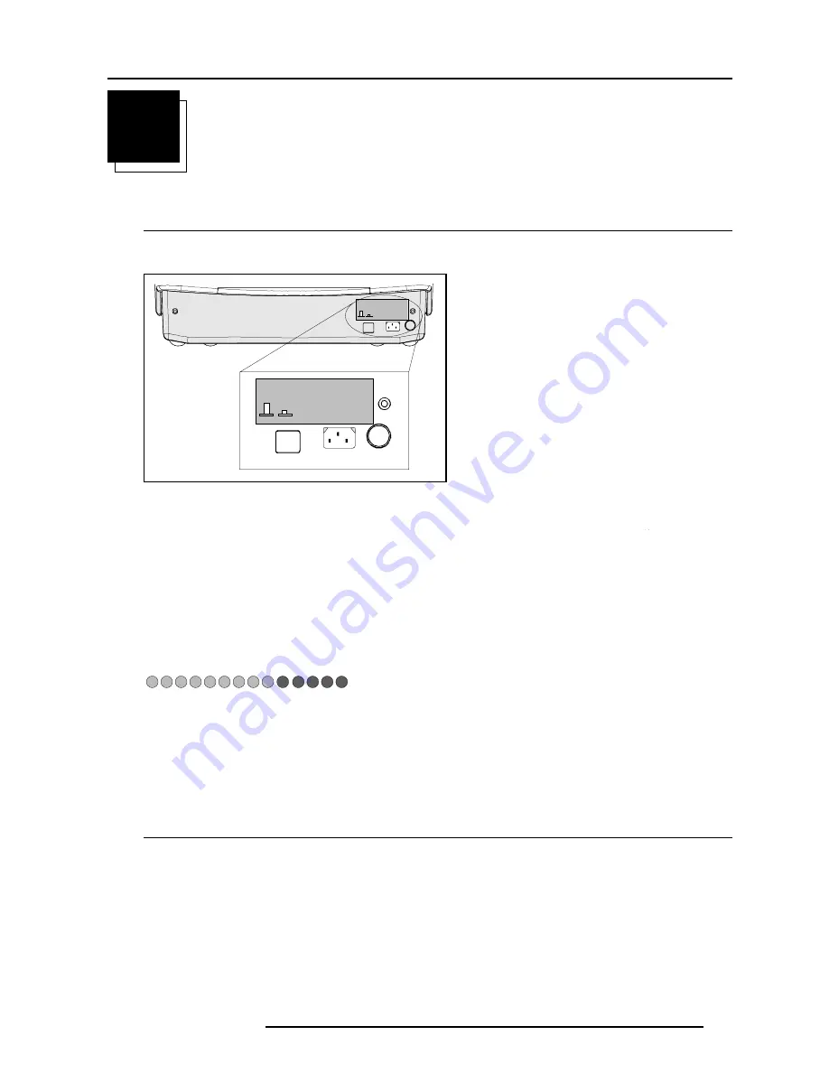
Power Connection to Projector

AC Power (mains) cord connection

Use the supplied power cord to connect your projector to the wall outlet.  Plug the female power connector into the male connector
at the front of the projector.

Leds on the front plate of the projector

Switching on/off

The projector is switched ON and OFF using the power (mains) switch ON/OFF.

Pressed : ON
Not pressed : OFF

The projector can start now in the 'operational mode' (image displayed) or in the 'stand by mode', depending on the software setup.

Stand by indication lamp :
no light up : projector in operational mode
red : projector is in stand by.

Input Source Connection

Input facilities

- Composite Video (*)
- S-Video (*)
- RGBS or RGsB (*)
- RGB3S or RG3sB
- (R-Y)Y(B-Y)S or (R-Y)Ys(B-Y) [component input] (**)
- (R-Y)Y(B-Y)3S or (R-Y)Y3s(B-Y) [component input] (**)

(*) If the line double  or line multiplier feature is built in, this feature is available via a software on/off toggle.
(**) If the line double or line multiplier feature is built in, this feature is available for component video signals on standard frequency via software on/off toggle.

OFF ON

See installation instructions before 

connecting to the supply

V NOM  120/230 Volt

I MAX     5/2.5 AMP

FREQ    60/50 Hz

OFF ON

See installation instructions before 

connecting to the supply

V NOM  120/230 Volt

I MAX     5/2.5 AMP

FREQ    60/50 Hz

-9V

HOLD 

DOWN 

HD

COINC

SF

HOLD 

DOWN 

EHT

STANDBY

-CONV

-17V

+17V

+HTHD

+CONV

+9V

+210V

+30V

Summary of Contents for R9002380

Page 1: ...BARCO PROJECTION SYSTEMS Date 08022000 OWNER S MANUAL Rev 01 Cin 7 R9002380 R9002381 R9002382 R9002387 R9002388 R9002389 Art No R5976066...

Page 2: ...the rights of their respective owners BARCOn v ProjectionSystems Noordlaan5 B 8520Kuurne Belgium Tel 32 56 368211 Fax 32 56 351651 E mail sales bps barco com Visite Barco at the web http www barco co...

Page 3: ...urce with composite sync 2 4 Connecting a RGB Analog source with Tri level sync 2 5 Connecting a Component source 2 6 Connecting a Component source with Tri level sync 2 7 RS232Connection 2 7 RS232 in...

Page 4: ...ne Doubler 5 2 Line Multiplier if available 5 2 Why Line Multiplying 5 2 How to change the Multiplier Setting 5 3 Line Multiplier ON OFF 5 3 MultiplierMode 5 3 What can be selected within the multipli...

Page 5: ...otection 6 1 Entering the password 6 2 RANDOM ACCESS ADJUSTMENT MODE 7 1 Random access adjustment mode 7 1 Starting Up 7 1 Overview Flowchart 7 1 Selecting Setup Pattern 7 2 Set up of the Selected Set...

Page 6: ...Advanced Settings 7 9 Why Time Base Correction 7 9 How to activate 7 9 Clamp Gating 7 10 Luminace Delay 7 10 Vertical Sync Reference 7 10 Factory Preset 7 11 Geometry Adjustments 7 11 What can be done...

Page 7: ...hat can be displayed 8 3 Note 8 3 How to start up 8 3 Changepassword 8 3 What can be done 8 3 Note 8 3 How to select 8 4 How to enter a new password 8 4 ChangeLanguage 8 4 What can be done 8 4 How to...

Page 8: ...1 What can be done 8 11 How to select 8 12 G2 Adjustment 8 12 CRT run in cycle 8 12 What can be done 8 12 How to select CRT run in cycle 8 12 Projector warm up 8 13 What can be done 8 13 How to select...

Page 9: ...t condition testing ensures the safety of the equipment to the user even when the equipment s normal operation fails INSTALLATIONINSTRUCTIONS Before operating this equipment please read this manual th...

Page 10: ...88 89 120V AC Consult your dealer to switch over from 230Vac to 120 Vac or from 120Vac to 230 Vac If you are not sure of the type of AC power available consult your dealer or local power company 2 Thi...

Page 11: ...ions since improper adjustment of the other controls may result in damage and will often require extensive work by a qualified technician to restore the product to normal operation e If the product ha...

Page 12: ...commended for proper room illumination Where possible care should also be taken to ensure that the floors and walls of the room in which the projector is to be installed are non reflecting dark surfac...

Page 13: ...perational mode red projector is in stand by Input Source Connection Input facilities Composite Video S Video RGBS or RGsB RGB3S or RG3sB R Y Y B Y S or R Y Ys B Y component input R Y Y B Y 3S or R Y...

Page 14: ...to disable this function enter the adjustment mode and change the position of the ON OFF toggle switch see chapter Random access adjustment mode TV tuner e g MARCO POLO VCR Audio amplifier Composite...

Page 15: ...for access to the local keypad see Local keypad in chapter getting Started 1 press ADJUST key the General access menu is displayed on the screen menu 1 2 use the cursor keys to highlight 1 3 press ENT...

Page 16: ...t A warning menu risk of incorrect adjustment will be displayed menu 2 4 Press ENTER to continue if you are qualified or EXIT if not When ENTER is pressed the Adjustment main menu will be displayed me...

Page 17: ...ss menu is displayed on the screen menu 1 2 Use the cursor keys to highlight 3 3 Press ENTER to display the source Connecting a RGB Analog source with Tri level sync RGB analog input terminals with Tr...

Page 18: ...e sync signal is located Line doubling or multipling is possible for component video input sources on standard line frequency Note If a line doubler or line multiplier is built in the default position...

Page 19: ...5 6 3 4 1 2 Enter ADJUST R Y Y B Y 3S or R Y Y3s B Y input selection a Press digit button 6 on the RCU or b With the local keypad to gain access to the local keypad see Local keypad in chapter gettin...

Page 20: ...RCVDS to control the projector source selection and analog settings The selected source number will be displayed on a 2 digit display and the selected input modules will be indicated with a LED on the...

Page 21: ...teries 1 Remove the battery cover on the backside by pushing the handle a little towards the bottom of the RCU 2 Lift up the top side of the cover at the same time 3 Push on the side of the battery to...

Page 22: ...ew of Functions This remote control includes a battery powered infrared IR transmitter that allows the user to control the projector remotely This remote control is used for source selection control a...

Page 23: ...g contrast during a meeting the displayed bar scale can be removed by pressing TEXT key first To re display the bar scale on the screen press TEXT key again 15 ENTER to start up the adjustment mode o...

Page 24: ...an reach its maximum specifications and minimize all distortions When starting this warm up period a full white image is shifted on the CRT faceplate to avoid a burn in Every 30 seconds a text box wil...

Page 25: ...nd the second side in the connector in the rear panel of the projector labelled REMOTE Projector address Why a projector address As more than one projector can be installed in a room the separate proj...

Page 26: ...R ADDRESS 001 To continue using the RCU with that specific address it is necessary to enter the same address with the digit buttons address between 0 and 9 within 5 seconds after pushing the address k...

Page 27: ...frequency Vertical frequency When the entry is a non valid source number a warning appears on the screen input not available WARNING input not available When a valid source number is selected the proj...

Page 28: ...Video Adjust the color saturation using the and buttons RCU or pushing the control disc to the left or to the right local keypad A bar scale gives a visual indication on the screen of the current col...

Page 29: ...6 3 4 1 2 Enter ADJUST GENERALACCESS Select with or then ENTER EXIT to return SHARPNESS TINT COLOR BRIGHTNESS CONTRAST 5 6 3 4 1 2 menu2 Select with or then ENTER EXIT to return MAIN MENU Image Contr...

Page 30: ...ment for the image IRIS Control This selection will only be available when the autoconvergence unit IRIS is built in into the projector This control will allow to align the projector automatically Sou...

Page 31: ...wchart MAIN MENU COLOR ADJUST FORMAT SELECT IRIS TOUCH UP IRIS AUTO CONVERGE NORMAL STEREO PSEUDO STEREO MONO SPATIAL STEREO IMAGE CONTROL IRIS CONTROL SOUND CONTROL IRIS FULL ALIGNMENT F1 F3 F4 F2 FU...

Page 32: ...hen LIMO is available Image Processing Line Doubler if available Why line doubling If a line doubler is built in the default position is ON When in the ON position the video input signals will be disp...

Page 33: ...or keys or to select Line Multiplier menu 1 2 Press ENTER to toggle between ON and OFF When in the ON state all multiplier functions are selectable MultiplierMode What can be selected within the multi...

Page 34: ...ssing menu 1 2 Press ENTER to toggle between ON and OFF menu1 Select with or then ENTER EXIT to return IMAGE PROCESSING Line Multiplier ON Multiplier Mode Motion Processing ON Video Equalizing Noise R...

Page 35: ...keys or to adjust the noise 4 Press ENTER to return to the Image Processing menu menu1 Select with or then ENTER EXIT to return IMAGE PROCESSING Line Multiplier ON Multiplier Mode Motion Processing O...

Page 36: ...FormatSelect What can be done For one source up to 8 different sets of settings can be stored A set of settings is called Format A Format can be available or free Available when settings are stored in...

Page 37: ...ailable xxxxxxxx Format 2 Free xxxxxxxx Fromat 3 Available BARCO Format 4 Free xxxxxxxx Format 5 Free xxxxxxxx Format 6 Free xxxxxxxx Format 7 Free xxxxxxxx Format 8 Free xxxxxxxx How to store the set...

Page 38: ...Converge 1 Push the cursor keys or to select IRIS Auto Converge menu 1 2 Press ENTER to activate the autoconvergence function The process starts and when successfully completed the projector will retu...

Page 39: ...be added to a function key To program a function key it is necessary to enter into the Service Menu To activate a function key just press the corresponding key The following functions are factory pre...

Page 40: ...f not EXIT to return 3 If qualified press ENTER menu 3 If not qualified press EXIT menu1 Select with or then ENTER EXIT to return MAIN MENU Image Control IRIS Control Sound Control Function keys Servi...

Page 41: ...he ADJUST key The projector displays the Main menu menu 2 2 Push the cursor keys or to select Service Menus 3 Press ENTER to select A warning will be displayed menu 3 4 If qualified press ENTER to con...

Page 42: ...8 9 4 5 6 1 2 3 0 Select with or then ENTER EXIT to return menu1 enter password xxxx Entering the password Your password contains 4 digits Entering via the RCU Enter the digits with the numeric keys...

Page 43: ...R LINEARITY COLOR BALANCE SYNC LINE DOUBLER MULTIPLIER ADJUSTMENT MODE Select a path from below IRIS GUIDED RANDOM ACCESS INSTALLATION SERVICE Source 01 DECODING PORT 2 Select with or then ENTER EXIT...

Page 44: ...ource is connected to the projector the internal cross hatch pattern menu will be displayed Note The menus in this manual are created for an external source connected to one of the inputs and the Genl...

Page 45: ...uts Color Balance Decoding Port 2 Video S Video Peaking Off Line Doubler Multiplier Geometry Convergence Color select And also Orbiting Contrast modulation Soft Edge if these options are installed Pic...

Page 46: ...ghlight Color Balance menu 1 2 Press ENTER to select The color balance menu will be displayed menu 2 menu1 menu2 Fixed Color Balance To select a fixed color balance handle as follow 1 Highlight one of...

Page 47: ...e sync function To change the Sync setting handle as follow 1 Push the cursor keys or to select Sync menu 1 2 Press ENTER to toggle between FAST and SLOW Note SYNC is normally used in the SLOW positio...

Page 48: ...s on standard line frequency and RGB signals on 15 kHz To eliminate the video line patterns and to improve the image stability the line doubler multiplier has to be switched on The line doubler multip...

Page 49: ...With this function it is possible to recognize whether the source material was originally film or video That prevents the creation of motion artifacts How to activate 1 Push the cursor keys or to sele...

Page 50: ...LIZING NOISE REDUCTION CONTRAST ENHANCEMENT ADVANCED SETTINGS menu1 menu2 VideoEqualizing What can be done The shapness of the image can be adjusted for 3 frequency bands low medium and high separatel...

Page 51: ...ENT SHOULD BE PERFORMED ONLY BY QUALIFIED PERSONNEL ContrastEnhancement What can be done Enhancing the contrast results in a more dynamic image How to select and adjust the contrast enhancement 1 Push...

Page 52: ...nd a line between the color is recognized How to adjust 1 Push the cursor key or to select Luminance delay menu 1 2 Press ENTER to activate 3 Push the cursor key or to adjust the luminance delay until...

Page 53: ...e Time base correction on Luminace delay 0 Vertical sync reference indirect Clamp gating off How to activate 1 Push the cursor key or to select Factory Preset menu 1 2 Press ENTER to activate menu1 Ge...

Page 54: ...ft to correct Note If the genlocked pattern was selected during the start up of the random access mode the external source will be displayed A bar scale and a number indicator between 0 and 100 on the...

Page 55: ...oid CRT damage do not shift the raster outside the phosphor area of the CRT menu1 menu2 image1 Left Right east west Adjustments What can be adjusted Left right and center adjustments affect only the v...

Page 56: ...ivate this function 3 Press EXIT to return Corrects for curvature of the vertical lines on the left side Correct by pushing the cursor keys to the right Correct by pushing the cursor keys to the left...

Page 57: ...formation by pushing the cursor key or until a straight line is obtained image 1 menu1 image1 Top Bottom north south Adjustments What can be adjusted Top Bottom and center adjustments affect only the...

Page 58: ...op and bottom of the image is visible proceed to the seagull correction Due to interaction it is possible that the top and bottom bow have to be readjusted after adjusting the seagull correction to ob...

Page 59: ...line is obtained image 1 menu1 image1 Size Adjustment What can be done To adjust correct a little bit the picture size when the projector is on its correct position in regard with the installed screen...

Page 60: ...nearity menu 1 2 press ENTER to activate menu 2 Adjust the vertical linearity with the cursor keys until the distances between the horizontal lines of the set up pattern are equal from top to bottom i...

Page 61: ...information is blanked out image 1 To enter a blanking alignment 1 Push the cursor key or to highlight the desired blanking position 2 Press ENTER to select 3 Press the cursor key or to adjust the bl...

Page 62: ...e green image and then on the blue image while superimposed on the green image The screen is devided into 25 areas image 1 Note The green convergence adjustments can be added as an option When these a...

Page 63: ...en ENTER EXIT to return Select with or then ENTER EXIT to return SERVICE MODE PROJECTOR SET UP MEMORY MANAGEMENT COMMON SETTINGS I2C DIAGNOSTICS SERVICE MODE IDENTIFICATION TOTAL RUN TIME CHANGE PASSW...

Page 64: ...E operating COMMON ADDRESS 0 BARCO LOGO menu1 menu2 Identification What can be seen The Identification screen gives information concerning Projector address To change the address of your projector con...

Page 65: ...er a burn in period of approximately 100 hours How to start up To select Total Run Time 1 Push the cursor key or to highlight Total Run Time menu 1 2 Press ENTER to activate The amount of time the pro...

Page 66: ...language of the screen menus to English Spanish French and German How to change the language To change the language handle as follow 1 Push the cursor key or to highlight Change Language menu 1 2 Pres...

Page 67: ...urn PROJECTOR SET UP IDENTIFICATION TOTAL RUN TIME CHANGE PASSWORD CHANGE LANGUAGE CHANGE PROJECTOR ADDRESS CHANGE BAUDRATE POWER UP MODE operating BARCO LOGO ENTER to accept EXIT to return BAUDRATE S...

Page 68: ...RCU is programmed with that common address every projector with that same common address will follow up the commands given by that RCU Why 2 different common address The reason to have the choice to s...

Page 69: ...go on the screen push the cursor key up down to the left or to the right until the desired position is reached OFF No BARCO logo displayed on the screen when leaving the adjustment mode Size SMALL LAR...

Page 70: ...3 15 6 50 intern FC 4 2 31 5 50 RGB3S FC 5 33 7 60 intern FC 6 7 8 Active block nr 1 DELETE BLOCK The selected block will be deleted ENTER to confirm EXIT to cancel menu1 menu2 menu3 Select with or th...

Page 71: ...LOCKS ALL SETTINGS TO MIDPOS R B CONVERGENCE MID GR CONVERGENCE MID SET TO MIDPOSITION All settings on current block will be overwritten ENTER to confirm EXIT to cancel All settings to midposition Wha...

Page 72: ...stead off R B convergence mid when this latter is pressed How to Undo 1 Push the cursor key or to highlight Undo R B convergence mid menu 1 2 Press ENTER execute the undo function R B convergence mid...

Page 73: ...Convergence settings in current block will be overwritten ENTER to confirm EXIT to cancel menu2 menu1 Undogreenconvergencemid What can be done Undo Gr convergence mid is displayed in the Memory manag...

Page 74: ...CRT run in cycle will start If no such a block is available the projector cannot run the CRT run in option and leaves the adjustment mode If you still want to run CRT run in cycle create first a memo...

Page 75: ...PROJECTOR WARM UP OPTION ON A FULL WHITE PATTERN WILL BE GENERATED FOR 20 MINUTES AT POWER UP AFTER THIS PROCEDURE THE PROJECTOR IS READY TO PERFORM IN OPTIMUM CONDITION TOGGLE OPTION ON OR OFF with...

Page 76: ...tings An on screen menu will give a indication of the memory bank nummer used To switch to another memory bank 1 Press ENTER to select the next memory bank in increasing order or 2 Enter the number of...

Page 77: ...R otherwise press EXIT and call for technical assistance 5 Select Random Access by pushing the cursor keys or 6 Press ENTER to display the Random Access mode menu menu 3 7 Push the cursor keys or to s...

Page 78: ...ht Bow Right Keystone Left Bow Left Keystone L R Seagull Correction Horizontal Centerline Bow Horizontal Centerline Skew Top Bow Top Keystone Bottom Keystone T B Seagull Correction IRIS Touch Up IRIS...

Page 79: ...ojector with the RCVDS this warning will be dis played when selecting an input slot of an RCVDS where the input board is missing WARNING source not available The input is a valid input but the source...

Page 80: ...6 BARCOCINE 7 011299 FAILURE RCVDS com munication error Serial communication error be tween the RCVDS and the projector FAN FAILED Projector will switch off Message when one of the fans are not workin...

Page 81: ...Number 01 Source Number 01 Horizontal Frequency 15 6 kHz Vertical Frequency 50 Hz Input Type video Scan Switch Configuration Front Ceiling The data representing the various adjustments for the source...

Page 82: ...ader A different analog settings source input 1 source number 1 source number 91 Block header B Block header B different analog settings source input 2 source input 9 source number 2 source number 92...

Reviews: