Lenses
C-1
5975348 BARCOVISION 8200 210497
C
LENSES
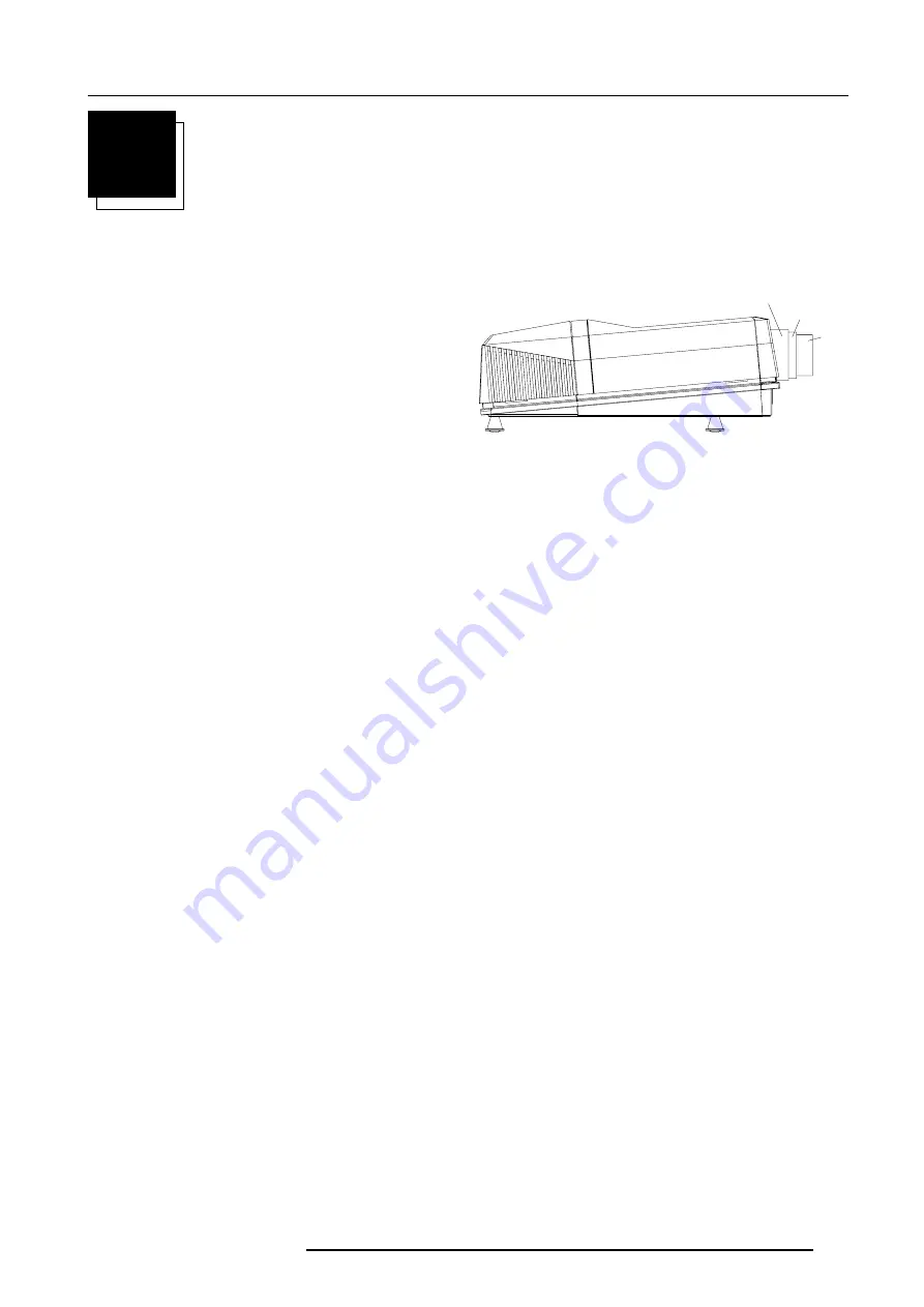
Focusing the lens
Loosen the fastener ring of the lens by turning counter clockwise.
Focus the image by turning the lens barrel to the left or the right.
Attention : Do not turn out the lens too far, otherwise it will fall out of
the lens holder.
When the image is focused, secure the correct position of the lens
with the fastener ring by turning this ring clockwise.
Lens Cleaning Procedure
Cleaning procedure for HD(1.5-3:1) lens and HD(3-5.3:1) lens.
To minimize the possibility of damaging the optical coating or scratch-
ing exposed lens surface, we have developed recommendations for
cleaning the lens. FIRST, we recommend you try to remove any
material from the lens by blowing it off with clean, dry deionized air.
DO NOT use any liquid to clean the lenses.
A Toraysee
TM
cloth is included with the lens kit.
Proceed as follows :
1. Always wipe lenses with a CLEAN Toraysee
TM
cloth.
2. Always wipe lenses in a single direction. Do not wipe back and
forward across the lens surface as this tends to grind dirt into the
coating.
3. Do not leave cleaning cloth in either an open room or lab coat
pocket, as doing so can contaminate the cloth.
4. If smears occur when cleaning lenses, replace the cloth. Smears
are the first indication of a dirty cloth.
5. Do not use fabric softener when washing the cleaning cloth or
softener sheets when drying the cloth.
6. Do not use liquid cleaners on the cloth as doing so will contaminate
the cloth.
Order number for a new Toraysee
TM
cloth : R379058.
Other lenses can also be cleaned safely with this Toraysee
TM
cloth.
Cleaning procedure for the other HD lens
To minimize the possibility of damaging the optical coating or scratch-
ing exposed lens surfaces, we have developed recommendations
for cleaning lenses.
FIRST
, we recommend you try to remove any
material from the lens by blowing it off with deionized air or
lightly
brushing it with a soft, camel's hair brush.
Plastic lens with multilayer coatings & all glass lens elements.
1.
DO NOT
spray any type of fluid directly on the lens surface.
2.
DO NOT
use any dry material to clean the surface (dry rag, tissue,
etc.)
3. Use a commercial liquid window cleaner.
DO NOT use an
aerosol.
Other cleaning agents, such as laboratory-grade acetone
or a 70-30 mixture of ethyl ether and ethyl alcohol may also be used.
If you are not sure of the cleaning agent, experiment with a small
area of the lens first.
4. Use a soft cotton cloth (cotton diapers laundered several times to
remove sizing) or any soft facial tissue (Charmin, Softweve, etc.).
5. When using window cleaner,
moisten the cloth or tissue
and
lightly wipe the surface. Then lightly dry with a new tissue.
6. When using acetone or ethyl ether mixture, proceed as follows :
Fold the cloth or tissue several times to form a pad. Soak the folded
end of the pad in the acetone. Starting at the diameter opposite you,
immediately wipe the coated lens, with very little pressure, toward
you in a straight line and off the lens. Do not stop with the tissue on
the lens. Wipe at a speed that is equal to the evaporation rate. This
is very important to prevent streaking and spotting. Start your
wiping at one side of the lens and, with successive wipes, move to
the other side. Turn the pad over for each wipe, then inside out. Do
not make more than one wipe per clean area of pad. Be careful of
the painted edge, since acetone will soften it.
Lens holder
Fastener
Lens