7. Advanced
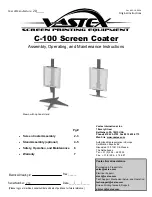
4. We start by setting both projectors to the common red coordinate.
Tip:
Draw a quick sketch of both gamuts as a graphical help.
650
640
310
320
330
660
R1
R2
Image 7-85
Red coordinates for both projectors
5. Display the internal color bar pattern on both projectors.
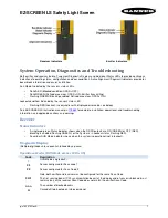
6. In the desired values, adjust the red coordinate to a common value for both projectors.
Tip:
The color bar of the adjusted coordinate will no longer be displayed in case the coordinate is not present within the gamut
of the adjusted projector e.g. with the desired values for red set to x=660 and y= 318.
650
640
310
320
330
660
R1
R2
Rc
Image 7-86
Coordinate is not present within the gamut of the adjusted projector
98
R5976992 ICON H250/400 13/12/2006
Summary of Contents for iCon H250
Page 1: ...iCon H250 400 Owners manual Preliminary R9010510 R9010500 R5976992 0A 13 12 2006...
Page 10: ...Table of contents 4 R5976992 ICON H250 400 13 12 2006...
Page 34: ...5 Connections 28 R5976992 ICON H250 400 13 12 2006...
Page 60: ...6 Setup 54 R5976992 ICON H250 400 13 12 2006...
Page 103: ...7 Advanced Image 7 84 R5976992 ICON H250 400 13 12 2006 97...
Page 130: ...8 Network centric operations 124 R5976992 ICON H250 400 13 12 2006...
Page 144: ...11 SNMP services 138 R5976992 ICON H250 400 13 12 2006...
Page 146: ...12 Maintenance 140 R5976992 ICON H250 400 13 12 2006...
Page 152: ...13 Image files 146 R5976992 ICON H250 400 13 12 2006...


![NEC MT800[1].PART1 User Manual preview](http://thumbs.mh-extra.com/thumbs/nec/mt800-1-part1/mt800-1-part1_user-manual_250403-1.webp)


