723
–
0018 /02
F70
24
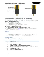
4.2 The DMD Device
DMD Device
Image 4-3
At the heart of every DLP
™
projection system is an optical semiconductor known as the Digital Micromirror
Device, or DMD chip, which was invented by Dr. Larry Hornbeck of Texas Instruments in 1987.
The DMD chip is probably the world's most sophisticated light switch. It contains a rectangular array of hinge-
mounted microscopic mirrors, each measuring less than one-fifth the width of a human hair, and
corresponding to one pixel in a projected image.
When a DMD chip is coordinated with a digital video or graphic signal, a light source, and a projection lens, its
mirrors can reflect an all-digital image onto a screen or other surface. The DMD and the sophisticated
electronics that surround it are what we call Digital Light Processing
™
technology.
The F70 / 90 DMD chip is part of the Texas Instrument DLP9000 family and features over 4 million
micromirrors on each chip, offering a dazzling high resolution 2560 x 1600 (WQXGA) array.
4.3 The Grayscale image
Grayscale
Image 4-4
Image 4-5
A DMD panel's micro-mirrors are mounted on tiny hinges that enable them to tilt either toward the light source
in a DLP
™
projection system (ON) or away from it (OFF)-creating a light or dark pixel on the projection
surface.
The bit-streamed image code entering the semiconductor directs each mirror to switch on and off up to several
thousand times per second. When a mirror is switched on more frequently than off, it reflects a light grey pixel;
a mirror that's switched off more frequently reflects a darker grey pixel.
In this way, the mirrors in a DLP
™
projection system can reflect pixels in up to 1,024 shades of grey to convert
the video or graphic signal entering the DMD into a highly detailed grayscale image.
Summary of Contents for F70 Series
Page 1: ...ENABLING BRIGHT OUTCOMES Service manual F70...
Page 8: ...723 0018 02 F70 8...
Page 11: ...11 723 0018 02 F70 General safety 2...
Page 14: ...723 0018 02 F70 14 General safety...
Page 21: ...21 723 0018 02 F70 DLP System General Description 4...
Page 26: ...723 0018 02 F70 26 DLP System General Description...
Page 36: ...723 0018 02 F70 36 GP7 system functional description...
Page 40: ...723 0018 02 F70 40 GP7 periodic maintenance...
Page 44: ...723 0018 02 F70 44 OSD display menu...
Page 53: ...723 0018 02 F70 53 Long Lifetime setting 0m asl Image 8 7 Thermal management system...
Page 54: ...723 0018 02 F70 54 Thermal management system...
Page 58: ...723 0018 02 F70 58 Lenses and adjustment...
Page 59: ...59 723 0018 02 F70 Optical adjustments 10...
Page 65: ...723 0018 02 F70 65 Image 11 2 Picture distortion Colorwheels...
Page 66: ...723 0018 02 F70 66 Colorwheels...
Page 67: ...67 723 0018 02 F70 Phosphor wheel 12...
Page 70: ...723 0018 02 F70 70 Phosphor wheel...
Page 71: ...71 723 0018 02 F70 Laser pulsing adjustment 13...
Page 74: ...723 0018 02 F70 74 Laser pulsing adjustment...
Page 79: ...79 Image 15 1 723 0018 02 F70 Power Supply Unit PSU 15...
Page 83: ...83 723 0018 02 F70 Troubleshooting 16...
Page 102: ...723 0018 02 F70 102 Troubleshooting...
Page 104: ...723 0018 02 F70 104 Image 17 1 Assembly hierarchy...
Page 113: ...723 0018 02 F70 113 Image 17 23 Assembly hierarchy...
Page 114: ...723 0018 02 F70 114 Assembly hierarchy...
Page 115: ...115 723 0018 02 F70 Scheduled operations 18...
Page 164: ...723 0018 02 F70 164 Image 22 14 Lens shift assembly...
Page 165: ...165 723 0018 02 F70 Prism Housing 23...
Page 167: ...723 0018 02 F70 167 Image 23 5 Prism Housing...