723
–
0018 /02
F70
31
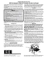
5.4 Wiring Matrix
Partnumber
Description
Quantity PCB Name
Conn. No. PCB Name
Conn. No.
534-0009-01
390 Switch Air
fi
lter
1
PCB Filter
J13
Switch Air
fi
lter
-
534-0001-04
390 Switch Thermal Le
ft
/
1
PCB Main
J8 ? J35 Switch T 535-0002-00
-
534-0011-00
390 Wobbulator
1
PCB TH
J33
Wobulator
-
534-0013-03
390 IR Front
1
PCB TH
J17
PCB IR Board
J1
PCB TH
J7
PCB Lens Shi
ft
J5
PCB TH
J40
PCB Lens Shi
ft
J5
534-0025-02
Cable Motor Illumina
ti
on
1
PCB TH
J4
Motor, Illumina
tti
n Iris
-
J1
J2
PCB Main
J27
PCB Temp Sense
J1
PCB Main
J28
PCB Temp Sense
J1
534-0053-00
395 Power Main
1
PCB Main
J30
PCB Power
J4
534-0054-00
395 Safety Bypass
1
PCB Main
J35
-
534-0055-00
534-0056-00
534-0057-00
395 CLO
1
PCB Hub
J30
PCB CLO
J1
534-0058-01
395 Comm PSU
1
PCB Main
J16
PCB PSU Main
J5
PCB Main
J1
PCB Hub
J11
PCB Main
J38
PCB Hub
J12
J4
PCB LD
J2
J63
(1 and 2)
J2
534-0061-00
395 Comm ph Wheel
1
PCB Main
J53
PCB CW Board
J1
534-0062-00
395 Comm Trigger and USB
1
PCB Hub
J10
PCB Trigger
J1
534-0063-00
395 Branch Inlet Fan
534-0064-00
PCB LD
J11
PCB Laser Blue
J1
(1 and 2)
J12
PCB Laser Blue
J1
J13
PCB Laser Blue
J1
J11
PCB Laser Blue
J1
J12
PCB Laser Blue
J1
J13
PCB Laser Blue
J1
534-0046-02
534-0026-01
395 Cable Motor Lens Shi
ft
1
534-0024-03
390 Lens
2
390 Temp Inlet Outlet
2
2
534-0060-00
395 Comm LD
534-0059-00
395 comm Hub Link 1/2
534-0065-00
395 Laser Driver Output
6
1
PCB Main
Comment: Connections will be self explanatory, due to cable length vs
connector distance.
PCB TH
Motor, Lens Shi
ft
h
-
Note: Cables with no Connec
ti
on 2, indicates that they ends up in a
complete module assy.
Cable art. no.,specifications, quantity
Connection 2
Connection 1
From
To
Cable Routing
Image 5-3: Cabling Matrix, part 1
Summary of Contents for F70 Series
Page 1: ...ENABLING BRIGHT OUTCOMES Service manual F70...
Page 8: ...723 0018 02 F70 8...
Page 11: ...11 723 0018 02 F70 General safety 2...
Page 14: ...723 0018 02 F70 14 General safety...
Page 21: ...21 723 0018 02 F70 DLP System General Description 4...
Page 26: ...723 0018 02 F70 26 DLP System General Description...
Page 36: ...723 0018 02 F70 36 GP7 system functional description...
Page 40: ...723 0018 02 F70 40 GP7 periodic maintenance...
Page 44: ...723 0018 02 F70 44 OSD display menu...
Page 53: ...723 0018 02 F70 53 Long Lifetime setting 0m asl Image 8 7 Thermal management system...
Page 54: ...723 0018 02 F70 54 Thermal management system...
Page 58: ...723 0018 02 F70 58 Lenses and adjustment...
Page 59: ...59 723 0018 02 F70 Optical adjustments 10...
Page 65: ...723 0018 02 F70 65 Image 11 2 Picture distortion Colorwheels...
Page 66: ...723 0018 02 F70 66 Colorwheels...
Page 67: ...67 723 0018 02 F70 Phosphor wheel 12...
Page 70: ...723 0018 02 F70 70 Phosphor wheel...
Page 71: ...71 723 0018 02 F70 Laser pulsing adjustment 13...
Page 74: ...723 0018 02 F70 74 Laser pulsing adjustment...
Page 79: ...79 Image 15 1 723 0018 02 F70 Power Supply Unit PSU 15...
Page 83: ...83 723 0018 02 F70 Troubleshooting 16...
Page 102: ...723 0018 02 F70 102 Troubleshooting...
Page 104: ...723 0018 02 F70 104 Image 17 1 Assembly hierarchy...
Page 113: ...723 0018 02 F70 113 Image 17 23 Assembly hierarchy...
Page 114: ...723 0018 02 F70 114 Assembly hierarchy...
Page 115: ...115 723 0018 02 F70 Scheduled operations 18...
Page 164: ...723 0018 02 F70 164 Image 22 14 Lens shift assembly...
Page 165: ...165 723 0018 02 F70 Prism Housing 23...
Page 167: ...723 0018 02 F70 167 Image 23 5 Prism Housing...