


5. Installation
5.5
Lamp recovery
About lamp recovery
When there was an external power failure and the power is coming up again, the projector lamp starts up
again in the same state as before the power failure.
The projector software has to know if the projector must remember its recovery settings.
About the use of an UPS system
When the projector is connected to an UPS system the electronics remains powered during an external
power failure. The lamp power supply is down and the lamp is out. When the external power is coming
up again, the lamp power supply starts again and the lamp starts in the same state as before the power
failure.
This UPS system reduces the restart of the complete system signi
fi
cantly.
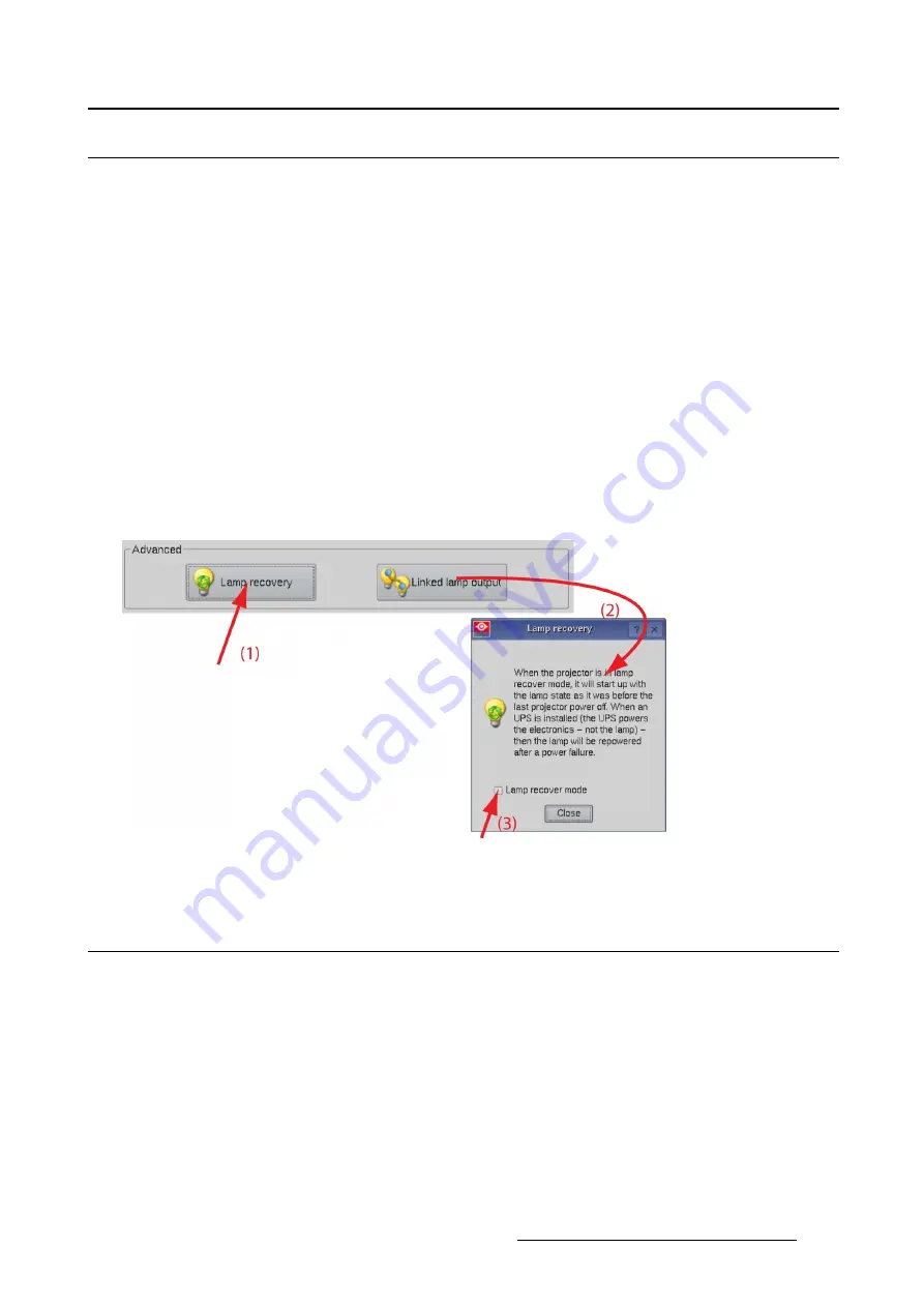
How to setup
1. While in
Installation
, tip
Lamp
and then tip
Lamp recovery
button (1). (image 5-16)
The
Lamp recovery
window opens (2).
2. To activate the lamp recovery mode, tip the check box next to
Lamp recover mode
.
Image 5-16
Lamp recovery
5.6
Linked lamp output
5.6.1
About linked lamp output
Goal
When 2 projectors are projecting on the same screen, e.g. for projecting 3D images, then it necessary
that both projectors are using the same light output, otherwise a difference in brightness will be visible
between both images.
To obtain this goal, one projector will be set as master and this master will manipulate the target CLO
value of the slave so that the lamp output will be aligned between both projectors. When the lamp output
of the master changes, then the lamp output of the slave will follow.
R59770488 COMMUNICATOR TOUCH PANEL 06/06/2012
135
Summary of Contents for DP2K Series
Page 1: ...Communicator Touch Panel User guide For DP2K DP4K series R59770488 05 06 06 2012 ...
Page 10: ...Table of contents Index 277 6 R59770488 COMMUNICATOR TOUCH PANEL 06 06 2012 ...
Page 36: ...2 Controls 32 R59770488 COMMUNICATOR TOUCH PANEL 06 06 2012 ...
Page 170: ...5 Installation Image 5 44 Image 5 45 166 R59770488 COMMUNICATOR TOUCH PANEL 06 06 2012 ...
Page 180: ...5 Installation Image 5 54 Cloning TI board 176 R59770488 COMMUNICATOR TOUCH PANEL 06 06 2012 ...
Page 201: ...5 Installation Image 5 76 Image orientation R59770488 COMMUNICATOR TOUCH PANEL 06 06 2012 197 ...
Page 202: ...5 Installation 198 R59770488 COMMUNICATOR TOUCH PANEL 06 06 2012 ...
Page 214: ...6 Maintenance Image 6 12 IP selection 210 R59770488 COMMUNICATOR TOUCH PANEL 06 06 2012 ...
Page 239: ...7 Touch panel Image 7 17 R59770488 COMMUNICATOR TOUCH PANEL 06 06 2012 235 ...
Page 245: ...7 Touch panel Image 7 23 Edit color palette R59770488 COMMUNICATOR TOUCH PANEL 06 06 2012 241 ...
Page 274: ...8 Macro editor 270 R59770488 COMMUNICATOR TOUCH PANEL 06 06 2012 ...
Page 280: ...A Source settings 276 R59770488 COMMUNICATOR TOUCH PANEL 06 06 2012 ...


