background image

7. Important information

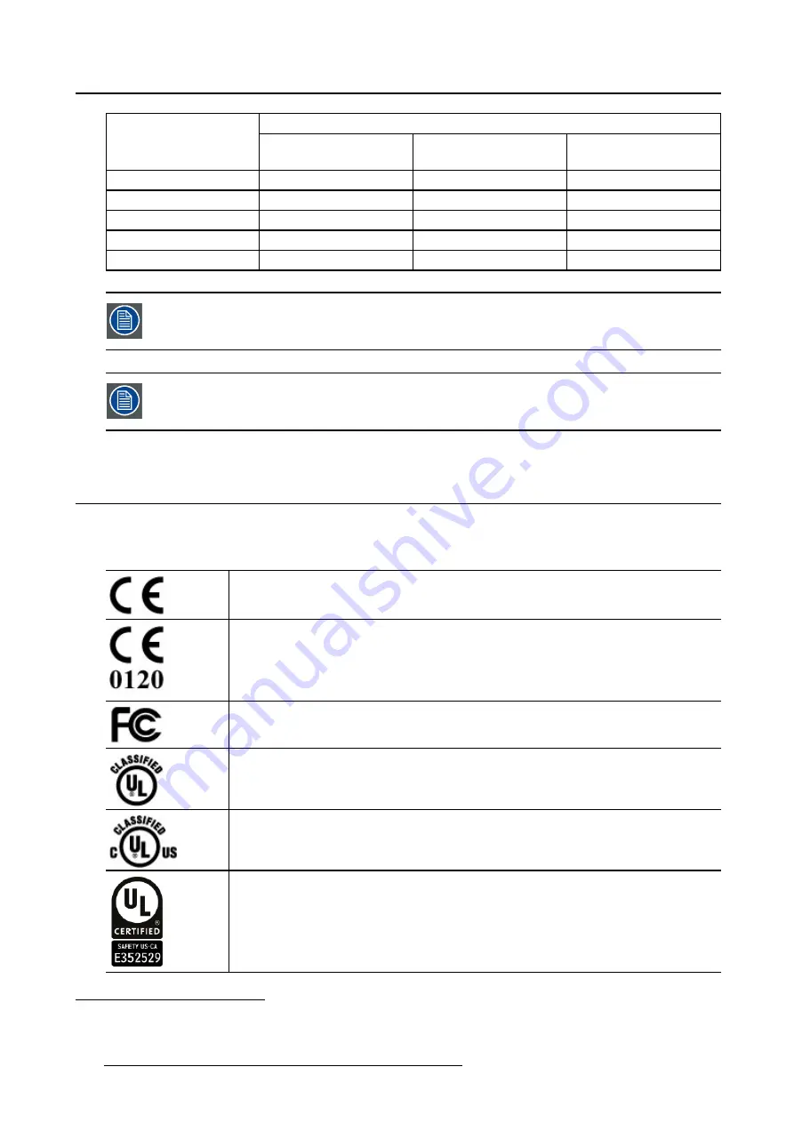
Separation distance according to frequency of transmitter

Rated maximum output
power of transmitter

5

W

150kHz to 80MHz

d=1.2

P

80MHz to 800MHz

d=1.2

P

800MHz to 2.5GHz

d=2.3

P

0.01

0.12

0.12

0.23

0.1

0.38

0.38

0.73

1

1.2

1.2

2.3

10

3.8

3.8

7.3

100

12

12

23

At 80 MHz and 800 MHz, the separation distance for the higher frequency range applies.

These guidelines may not apply in all situations. Electromagnetic propagation is af-
fected by absorption and re

fl

ection form structures, object and people.

7.5

Explanation of symbols

Symbols on the device

On the device or power supply, you may

fi

nd the following symbols (nonrestrictive list):

Indicates compliance with the Directive 93/42/EEC as Class I device

Indicates compliance with the Directive 93/42/EEC as Class II device

Indicates compliance with Part 15 of the FCC rules (Class A or Class B)

Indicates the device is approved according to the UL regulations

Indicates the device is approved according to the UL regulations for Canada
and US

Indicates the device is approved according to the UL regulations for Canada
and US

5. For transmitters rated at a maximum output power not listed above, the recommended separation distance d in meters (m) can be

estimated using the equation applicable to the frequency of the transmitter. Where P is the maximum output power rating of the

transmitter in watts (W) according to the transmitter manufacturer.

54

K5902079 CORONIS UNITI 21/04/2015

Summary of Contents for Coronis Uniti MDMC-12133

Page 1: ...Coronis Uniti User Guide MDMC 12133 K5902079 03 21 04 2015...

Page 2: ...Barco nv President Kennedypark 35 8500 Kortrijk Belgium Phone 32 56 23 32 11 Fax 32 56 26 22 62 Support www barco com en support Visit us at the web www barco com Printed in Belgium...

Page 3: ...n 23 4 2 Key indicator lights 24 4 3 Standby switching 24 4 4 Bringing up the OSD menus 25 4 5 Navigating through the OSD menus 25 4 6 Overview of the functionality of the Left Right keys 26 4 7 I Lum...

Page 4: ...t interface standard version 41 5 26 EDID format 42 5 27 EDID timings 42 5 28 Display info 42 5 29 Display status 43 6 Cleaning your display 45 6 1 Cleaning instructions 45 7 Important information 47...

Page 5: ...your entire field of view Use the instructions in this guide to install your Coronis Uniti display and discover the productive features and included accessories CAUTION Read all the important safety i...

Page 6: ...1 Welcome 4 K5902079 CORONIS UNITI 21 04 2015...

Page 7: ...S 2 1 Display front view Overview Image 2 1 Front view 1 I Luminate Left key 2 Right key 3 Menu key 4 Standby key 5 Power status indicator light Power On 6 Power status indicator light Standby 7 I Gua...

Page 8: ...compartment cover 1 Connector compartment cover 2 Tilt lock pin only for transportation 3 Tilt swivel foot 4 Cable duct 5 Foot lock pin only for transportation 6 SoftGlow Task light 7 SoftGlow Wall li...

Page 9: ...lay port connector 3 Display port connector 4 Not used 5 USB upstream connector 6 USB downstream connector 7 USB downstream connector 8 USB downstream connector 2 3 Accessories Film clip The film clip...

Page 10: ...2 Parts controls and connectors MultiTouchPad The MultiTouchPad enables and controls SpotView Image 2 5 MultiTouchPad 8 K5902079 CORONIS UNITI 21 04 2015...

Page 11: ...ollers please refer to the latest version of the com patibility matrix available on my barco com MyBarco My Support Healthcare Com patibility Matrices Barco Systems Compatibility Matrices 3 1 Removing...

Page 12: ...ith its rear side facing you 2 Pull out the red pin in the display stand 3 Keep the pin in case the display needs to be shipped later WARNING Before transportation of the display insert the pin in the...

Page 13: ...to the stand of your display 3 4 Adjusting the display position In the factory the height positioning and the tilt system in the display stand are locked with red pins to prevent damage during transpo...

Page 14: ...and 3 5 Connecting the signal cables To get access to the connectors remove the connector compartment cover See Re moving the connector compartment cover page 9 To connect the signal cables to the dis...

Page 15: ...isplay controller to the other DisplayPort connector with one of the sup plied DisplayPort cables 3 Connect a PC USB downstream connector to the display s USB upstream connector by means of the suppli...

Page 16: ...it is recommended to use the USB upstream connector for faster communication 3 6 Connecting the power cable To connect the power cable to the display 1 Connect the supplied external DC power supply to...

Page 17: ...proper power cord delivered in the packaging Use the external power supply delivered with your display If you do not use the correct power supply the display will not start up 3 7 Mounting the film cl...

Page 18: ...nectors using either those found in the cable compartment or on the right side of the display 2 With the MultiTouchPad attached and the driver installed simply press on the MultiTouchPad to move the f...

Page 19: ...ur display Tip The cable straps at the inside of the connector compartment allow you to fix the cables for better shielding of the cables To reattach the connector compartment cover 1 Reattach the con...

Page 20: ...tion 3 10 Fixation of the foot on the desk Overview If you would like to attach the Coronis Uniti to a desk the tilt swivel foot has 4 screw holes 4x M4 to mount the foot on a desk 18 K5902079 CORONIS...

Page 21: ...tached to an arm by pulling or pushing the display itself Instead make sure that the arm is equipped with a VESA approved handle and use this to move the display Please refer to the instruction manual...

Page 22: ...th the VESA 200 x 100 mm and VESA 100 x100 mm standard So it can be used with an arm stand according to the VESA 200 x 100 mm or VESA 100 x 100 mm standard Therefore the tilt swivel foot must be remov...

Page 23: ...3 Display installation 4 Remove the two plastic covers 5 Remove the 9 screws fixing the foot while supporting the foot K5902079 CORONIS UNITI 21 04 2015 21...

Page 24: ...for the first time 1 Switch on your Coronis Uniti as described in Standby switching page 24 2 Turn on the computer connected to your display If you have properly installed your display and display co...

Page 25: ...on usage A good screen saver displays moving content In case you are working with the same image or an application with static image elements for several hours continuously so that the screen saver is...

Page 26: ...further actions are taken within the following 5 seconds the keys will dim again The I Luminate Left key is always lit and available for activation of the I Luminate fea ture Please refer to I Luminat...

Page 27: ...the OSD menus can be done by 1 If not already done so switch on the display as previously described 2 Illuminate the keys as previously described 3 While the keys are illuminated touch the menu key A...

Page 28: ...ight key Behavior Push Push Cycle viewing mode between text diagnostic Toggle on I Luminate Left key Right key Menu Behavior Push No push No menu Toggle off I Luminate No push Push No menu Cycle I Lum...

Page 29: ...extended display keypad functions The concept of the extended display keypad functions is to present a selection of functions immediately available to the user without the need to navigate through the...

Page 30: ...4 Daily operation 28 K5902079 CORONIS UNITI 21 04 2015...

Page 31: ...ed To enable disable the OSD menu automatic close function 1 Bring up the OSD main menu 2 Navigate to the Configuration User Interface Menu menu 3 Enter the Automatic Close submenu 4 Select Enabled Di...

Page 32: ...k function is disabled again To enable disable the power lock function 1 Bring up the OSD main menu 2 Navigate to the Configuration User Interface Controls menu 3 Enter the Power Lock submenu 4 Select...

Page 33: ...de About DPMS mode Enabling the Display Power Management System DPMS mode on your display will optimize its diagnos tic lifetime by automatically switching off the backlight when the display is not us...

Page 34: ...imeout 1 Bring up the OSD main menu 2 Navigate to the Configuration Power Management menu 3 Enter the Hibernate Timeout submenu 4 Set the timeout value as desired and confirm 5 10 I Luminate default m...

Page 35: ...ght to reach the target To set the luminance target 1 Bring up the OSD main menu 2 Navigate to the Configuration Calibration menu 3 Enter the Luminance Target submenu 4 Set a luminance target value as...

Page 36: ...5 Enter the Color Temperature submenu 6 Set the Temperature value as desired and confirm 5 15 Color coordinates About color coordinates It is possible to change the color coordinates of your display C...

Page 37: ...ay all grayscale color levels with luminance increments that are not optimal for crucial diagnostic information Studies have shown however that in medical images certain grayscale color parts contain...

Page 38: ...ant to select a realistic reading room when enabling ALC This can be done by following the instruc tions in Reading rooms page 36 To enable disable ALC 1 Bring up the OSD main menu 2 Navigate to the C...

Page 39: ...mbient light To select a reading room 1 Bring up the OSD main menu 2 Navigate to the Configuration Calibration Ambient Light menu 3 Enter the Reading Room submenu 4 Select one of the available reading...

Page 40: ...s from the moment it is installed and running MediCal QAWeb Agent will take over from Embedded QA and overwrite any settings which were applied by Embedded QA 5 21 2 DICOM status report About DICOM st...

Page 41: ...ck Warning Pressing a key during the compliance check will abort the check 5 21 4 DICOM calibration About DICOM calibration The DICOM calibration will add a correction to the current DICOM curve to ap...

Page 42: ...age Source menu 3 Enter the Scaling submenu 4 Select Enabled Disabled as desired and confirm 5 23 Image source selection modes About image source selection modes Your Coronis Uniti automatically detec...

Page 43: ...isplay controller is converted to grayscale in your display The available grayscale conversion modes are No Conversion Use Red Channel This mode is intended for grayscale displays where gray is sent o...

Page 44: ...sh rate of the image source video input signal depending on the maximum refresh rate of the display controller connected to your display Color Depth Allows to change the color depth to 8 or to 10 bit...

Page 45: ...onnected image sources video encoding mode timings etc the current calibration status of your display display function luminance ALC etc and the status about activated connections To retrieve the stat...

Page 46: ...5 Advanced operation 44 K5902079 CORONIS UNITI 21 04 2015...

Page 47: ...lcohol solvents at higher concentration 5 Strong alkalis lye strong solvents Acid Detergents with fluoride Detergents with ammonia Detergents with abrasives Steel wool Sponge with abrasives Steel blad...

Page 48: ...6 Cleaning your display 46 K5902079 CORONIS UNITI 21 04 2015...

Page 49: ...Non patient care equipment Equipment primarily for use in a health care facility that is intended for use where contact with a patient is unlikely no applied part The equipment may not be used with li...

Page 50: ...ht of at least 3 devices If you use an unstable cart or stand the device may fall causing serious injury to a child or adult and serious damage to the device This apparatus conforms to IEC 60950 1 200...

Page 51: ...S of Chinese Mainland the table below lists the names and contents of toxic and or hazardous substances that Barco s product may contain The RoHS of Chinese Mainland is included in the MCV standard of...

Page 52: ...w analysis and diagnosis by trained medical practitioners It is especially designed for breast tomosynthesis applications Caution USA Federal law restricts this device to sale by or on the order of a...

Page 53: ...r its internal function Therefore its RF emissions are very low and are not likely to cause any interference in nearby electronic equipment RF emissions CISPR 11 Class B Harmonic emissions IEC 61000 3...

Page 54: ...for 0 5 cycle 40 UT 60 dip in UT for 5 cycles 70 UT 30 dip in UT for 25 cycles 5 UT 95 dip in UT for 5s 5 UT 95 dip in UT for 0 5 cycle 40 UT 60 dip in UT for 5 cycles 70 UT 30 dip in UT for 25 cycle...

Page 55: ...e controlled The customer of the user of the Coronis Uniti can help prevent electromagnetic interfer ence by maintaining a minimum distance between portable and mobile RF communications equipment tran...

Page 56: ...ing symbols nonrestrictive list Indicates compliance with the Directive 93 42 EEC as Class I device Indicates compliance with the Directive 93 42 EEC as Class II device Indicates compliance with Part...

Page 57: ...tions Indicates the device is approved according to the PSE regulations Indicates the USB connectors on the device Indicates the DisplayPort connectors on the device Indicates the legal manufacturer I...

Page 58: ...c for use only under the specific terms of a software license agreement between Barco N V or Barco Inc and the licensee No other use duplication or disclosure of a Barco software product in any form i...

Page 59: ...downstream USB standard 2 0 Power requirements nominal 100 240 V Power consumption nominal 190 W Power save mode Yes Power management VESA DPMS Dot clock 195 MHz OSD languages English German French Du...

Page 60: ...en Source license A copy of the source code is available on request by contacting your Barco customer support representative EACH SEPARATE OPEN SOURCE SOFTWARE COMPONENT AND ANY RELATED DOCUMENTA TION...

Reviews: