9. Image menu
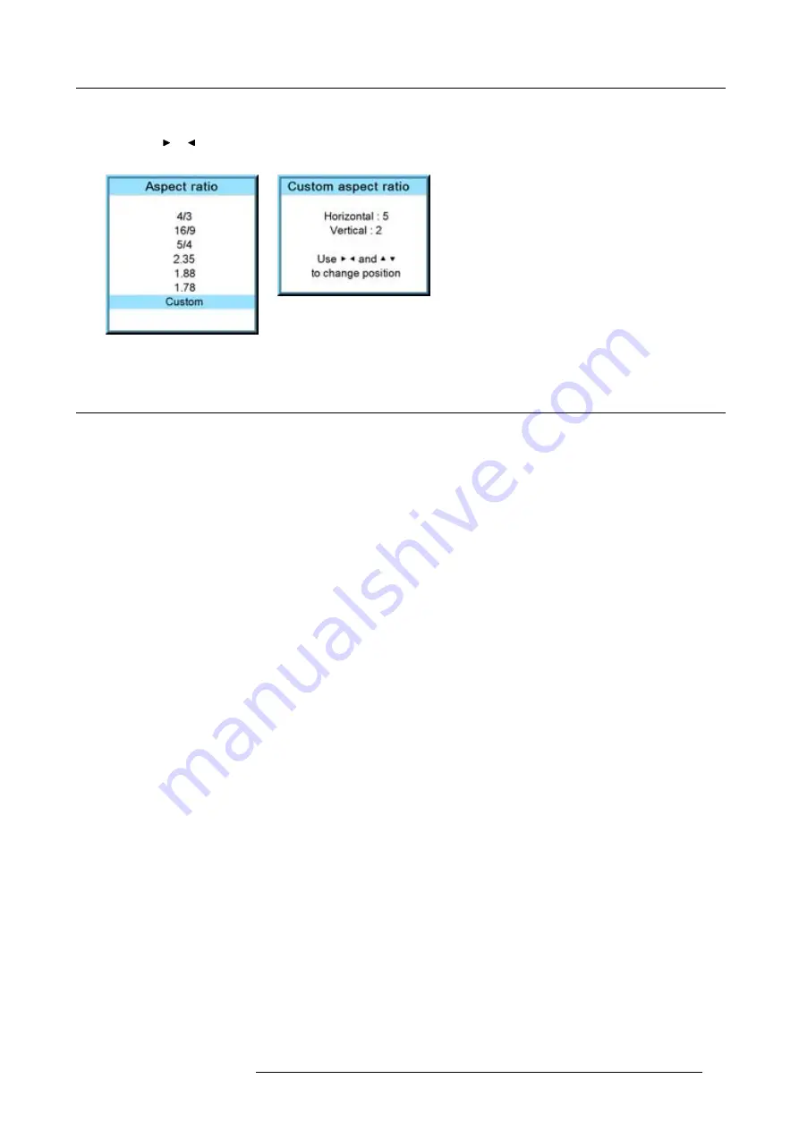
The
Custom aspect ratio
dialog box opens.
2. Use the
▲
or
▼
key to adjust the vertical size of the image.
Use the
or
key to adjust the horizontal size of the image.
When the desired aspect ratio is obtained, press
EXIT
Image 9-60
Image 9-61
9.5
Timings
9.5.1
Source timings
Adjustable items
•
Horizontal start in pixels : number of pixels between the beginning of the input signal and the start of the video information in
the signal.
•
Width = Active horizontal pixels : determine the width of the window on the screen. This value is normally given in the source
speci
fi
cations. If not, adjust until full image is displayed (no missing pixels).
•
Vertical start in lines : number of lines between the start of the input signal and start of the image on the screen.
•
Height = Active vertical lines : number of horizontal lines determining the height of the projected image. this value is normally
given in the speci
fi
cation of the source. If not, adjust until full image height is displayed (no missing lines).
•
Total pixels: Total horizontal pixels in the source. If the value is wrong, sampling mistakes (small vertical bars in the projected
image) will be seen in the image.
•
Total lines: Total vertical lines in the source.
How to start up?
1. Press
MENU
to activate the menus.
2. Use the
▲
or
▼
key to select
Image
and press
ENTER
.
3. Use the
▲
or
▼
key to select
Timings
and press
ENTER
.
The timings menu will be displayed. (image 9-62, image 9-63, image 9-64)
4. To change a setting, use the
▲
or
▼
key to select and press
ENTER
.
The corresponding adjustment box is displayed. E.g. Horizontal total pixels. (image 9-65)
5. Use the
▲
or
▼
key (or
◄
or
►
key) to change the value.
6. Press
ENTER
to activate the new value.
7. If necessary to change other settings, repeat from step 4.
R59770021 CLM R10+ 11/10/2010
87
Summary of Contents for CLM R10+
Page 1: ...CLM R10 Users manual R9050100 R90501001 R90501005 R59770021 11 11 10 2010 ...
Page 14: ...1 Safety 10 R59770021 CLM R10 11 10 2010 ...
Page 22: ...2 General 18 R59770021 CLM R10 11 10 2010 ...
Page 36: ...3 Physical installation 32 R59770021 CLM R10 11 10 2010 ...
Page 41: ...4 Stacking CLM projectors Zoom Image 4 9 Zoom adjustment R59770021 CLM R10 11 10 2010 37 ...
Page 42: ...4 Stacking CLM projectors 38 R59770021 CLM R10 11 10 2010 ...
Page 50: ...5 Connections 46 R59770021 CLM R10 11 10 2010 ...
Page 66: ...7 Start up of the Adjustment mode 62 R59770021 CLM R10 11 10 2010 ...
Page 75: ...8 Input menu Image 8 26 Image 8 27 Image 8 28 R59770021 CLM R10 11 10 2010 71 ...
Page 76: ...8 Input menu 72 R59770021 CLM R10 11 10 2010 ...
Page 102: ...9 Image menu 98 R59770021 CLM R10 11 10 2010 ...
Page 169: ...14 Service menu Image 14 55 Image 14 56 Image 14 57 R59770021 CLM R10 11 10 2010 165 ...
Page 170: ...14 Service menu 166 R59770021 CLM R10 11 10 2010 ...
Page 184: ...16 Servicing 180 R59770021 CLM R10 11 10 2010 ...
Page 194: ...17 Projector covers removal and installation 190 R59770021 CLM R10 11 10 2010 ...
Page 202: ...C DMX Chart 198 R59770021 CLM R10 11 10 2010 ...
Page 212: ...E Troubleshooting 208 R59770021 CLM R10 11 10 2010 ...
Page 218: ...F Mounting optional Carry handle 214 R59770021 CLM R10 11 10 2010 ...
Page 220: ...G Order info 216 R59770021 CLM R10 11 10 2010 ...


