13. Projector control
Default Gateway
A router that serves as an entry point into and exit point out of a network. For example, a local network (LAN) may
need a gateway to connect it to a wide area network (WAN) or to the Internet.
MAC address
Media Access Control address. Unique hardware number, used in combination with the IP-address to connect to the
network (LAN or WAN).
What should be set up for an Ethernet address?
2 ways can be used to assign an address:
•
use the DHCP setting so that an automatic address will be assigned.
•
Assign manually an IP address, Net-mask (subnet-mask), (default) gateway address.
-
Set the IP-Address
fi
eld to the desired value. This must NOT be 0.0.0.0 for static IP-Address assignment. The IP address
identi
fi
es a projector’s location on the network in the same way a street address identi
fi
es a house on a city block. Just as
a street address must identify a unique residence, an IP address must be globally unique and have a uniform format.
-
Set the Subnet-Mask as appropriate for the local subnet.
-
Set the Default-Gateway to the IP-Address of the local router (MUST be on the local subnet!) on the same network as this
projector that is used to forward traf
fi
c to destinations beyond the local network. This must not be 0.0.0.0. If there is no
router on the projector’s local subnet then just set this
fi
eld to any IP-Address on the subnet.
13.4.2 DHCP setup
How to switch DHCP setting?
1. Press
MENU
to activate the menus.
2. Use the
▲
or
▼
key to select
Projector control
and press
ENTER
.
3. Use the
▲
or
▼
key to select
Ethernet
and press
ENTER
.
The Ethernet menu opens.
4. Use the
▲
or
▼
key to select
DHCP
.
5. Press
ENTER
to toggle the DHCP setting.
[ON] = DHCP is activated. Automatic assigning of an address is activated.
[OFF ] = DHCP is deactivated. A
fi
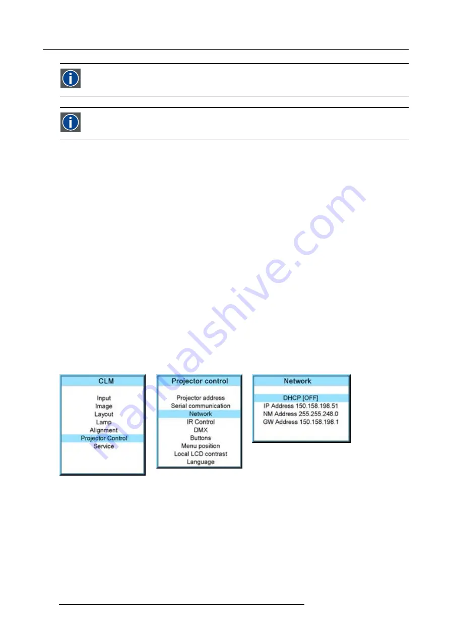
xed address will be used. (image 13-18, image 13-19, image 13-20)
Image 13-18
Image 13-19
Image 13-20
13.4.3 IP-address set up
How to set up?
1. Press
MENU
to activate the menus.
2. Use the
▲
or
▼
key to select
Projector control
and press
ENTER
.
3. Use the
▲
or
▼
key to select
Network
and press
ENTER
.
The Network menu opens.
142
R59770021 CLM R10+ 11/10/2010
Summary of Contents for CLM R10+
Page 1: ...CLM R10 Users manual R9050100 R90501001 R90501005 R59770021 11 11 10 2010 ...
Page 14: ...1 Safety 10 R59770021 CLM R10 11 10 2010 ...
Page 22: ...2 General 18 R59770021 CLM R10 11 10 2010 ...
Page 36: ...3 Physical installation 32 R59770021 CLM R10 11 10 2010 ...
Page 41: ...4 Stacking CLM projectors Zoom Image 4 9 Zoom adjustment R59770021 CLM R10 11 10 2010 37 ...
Page 42: ...4 Stacking CLM projectors 38 R59770021 CLM R10 11 10 2010 ...
Page 50: ...5 Connections 46 R59770021 CLM R10 11 10 2010 ...
Page 66: ...7 Start up of the Adjustment mode 62 R59770021 CLM R10 11 10 2010 ...
Page 75: ...8 Input menu Image 8 26 Image 8 27 Image 8 28 R59770021 CLM R10 11 10 2010 71 ...
Page 76: ...8 Input menu 72 R59770021 CLM R10 11 10 2010 ...
Page 102: ...9 Image menu 98 R59770021 CLM R10 11 10 2010 ...
Page 169: ...14 Service menu Image 14 55 Image 14 56 Image 14 57 R59770021 CLM R10 11 10 2010 165 ...
Page 170: ...14 Service menu 166 R59770021 CLM R10 11 10 2010 ...
Page 184: ...16 Servicing 180 R59770021 CLM R10 11 10 2010 ...
Page 194: ...17 Projector covers removal and installation 190 R59770021 CLM R10 11 10 2010 ...
Page 202: ...C DMX Chart 198 R59770021 CLM R10 11 10 2010 ...
Page 212: ...E Troubleshooting 208 R59770021 CLM R10 11 10 2010 ...
Page 218: ...F Mounting optional Carry handle 214 R59770021 CLM R10 11 10 2010 ...
Page 220: ...G Order info 216 R59770021 CLM R10 11 10 2010 ...


