9. Image menu
9.3.9.2
Adjusting the input balance
How can it be done ?
To balance the three color signals of a particular source there are conditions; in fact we must know the black and the white level of
the source i.e. :
1.
The source in question must be able to generate a white signal, ideally a 100% white (background) full screen pattern
2.
The source in question must be able to generate a black signal, ideally a 100% black (background) full screen pattern
A
B
Image 9-44
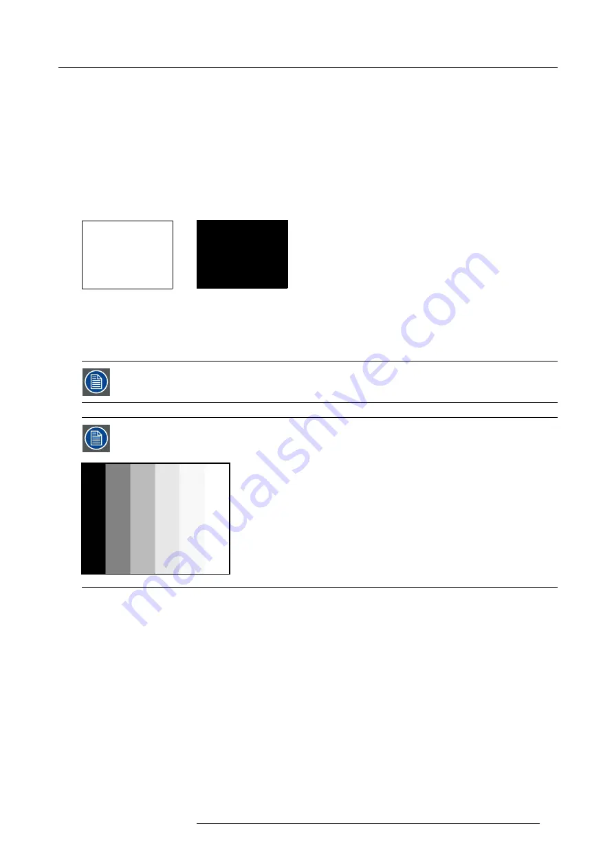
White balance : In the projector, we will set the contrast for each color until we get a 100% light output picture when projecting a
100% white image (image A)
Black balance : In the projector, we will set the brightness for each color until we get a 0% light output picture when projecting a
100% black image (image B).
The changeover from min to max is indicated by the apparition of bright spots also called “digital noise”
An alternative to a full screen White/black pattern is the standard gray scale pattern, the white bar will be used
for white balance and the black bar for black balance.
Image 9-45
Black balance
1. Press
MENU
to activate the menus.
2. Use the
▲
or
▼
key to select
Image
and press
ENTER
.
3. Use the
▲
or
▼
key to select
Image settings
and press
ENTER
.
4. Use the
▲
or
▼
key to select
Input balance
and press
ENTER
.
5. Do you want to use an internally generated test pattern ?
If yes, Use the
▲
or
▼
key to select
Test pattern
and press
ENTER
to toggle between [on] and [off]
If no, Adjust on the selected source.
6. Use the
▲
or
▼
key to select
Black balance
and press
ENTER
.
Depending whether a test pattern is selected or not, the adjustment image is displayed.
7. Toggle with
▲
or
▼
key to select
Black balance red
. (image 9-46, image 9-47, image 9-48, image 9-49, image 9-50)
8. Adjust the red black level on a minimal value
R59770021 CLM R10+ 11/10/2010
83
Summary of Contents for CLM R10+
Page 1: ...CLM R10 Users manual R9050100 R90501001 R90501005 R59770021 11 11 10 2010 ...
Page 14: ...1 Safety 10 R59770021 CLM R10 11 10 2010 ...
Page 22: ...2 General 18 R59770021 CLM R10 11 10 2010 ...
Page 36: ...3 Physical installation 32 R59770021 CLM R10 11 10 2010 ...
Page 41: ...4 Stacking CLM projectors Zoom Image 4 9 Zoom adjustment R59770021 CLM R10 11 10 2010 37 ...
Page 42: ...4 Stacking CLM projectors 38 R59770021 CLM R10 11 10 2010 ...
Page 50: ...5 Connections 46 R59770021 CLM R10 11 10 2010 ...
Page 66: ...7 Start up of the Adjustment mode 62 R59770021 CLM R10 11 10 2010 ...
Page 75: ...8 Input menu Image 8 26 Image 8 27 Image 8 28 R59770021 CLM R10 11 10 2010 71 ...
Page 76: ...8 Input menu 72 R59770021 CLM R10 11 10 2010 ...
Page 102: ...9 Image menu 98 R59770021 CLM R10 11 10 2010 ...
Page 169: ...14 Service menu Image 14 55 Image 14 56 Image 14 57 R59770021 CLM R10 11 10 2010 165 ...
Page 170: ...14 Service menu 166 R59770021 CLM R10 11 10 2010 ...
Page 184: ...16 Servicing 180 R59770021 CLM R10 11 10 2010 ...
Page 194: ...17 Projector covers removal and installation 190 R59770021 CLM R10 11 10 2010 ...
Page 202: ...C DMX Chart 198 R59770021 CLM R10 11 10 2010 ...
Page 212: ...E Troubleshooting 208 R59770021 CLM R10 11 10 2010 ...
Page 218: ...F Mounting optional Carry handle 214 R59770021 CLM R10 11 10 2010 ...
Page 220: ...G Order info 216 R59770021 CLM R10 11 10 2010 ...


