background image

P/N 128185 Rev A

Banner Engineering Corp. • Minneapolis, MN U.S.A.

www.bannerengineering.com  •  Tel: 763.544.3164

SureCross™ DX80 Quick Start Guide

21

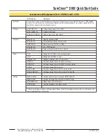
Model Number

Description

Antennas

Banner offers a range of omni-directional and directional (Yagi) antennas for use with the SureCross™ DX80 wireless 
network. For more information on antenna specifications and the options available for your system, please contact the 
applications engineers at Banner Engineering Corp.

O-Rings

BWA-ORING-001

O-Ring, Rotary Access Cover, PG21

BWA-GASKET-001

O-Ring, Body Gasket

BWA-CLRCOVER-001

Rotary Access Cover, Clear Plastic

Hardware

BWA-HW-001

Mounting Hardware, DX80

BWA-HW-002

Access Hardware (Plugs, Glands), DX80

SMBDX80DIN

Bracket Assembly, DIN Rail, for DX80

BWA-HW-003

Tape, PFTE Sealant

BWA-HW-004

Screws, Cover Mount, #8-32 x 3/4, 18-8 SS

Power

DX81

Battery Pack Kit, DX81, with mounting hardware

DX121

Battery Pack Kit, DX121, 6 cells

BWA-BATT-001

Replacement Battery, 3.6V, “D” Lithium Cell

SPS101Q

DC Power Supply, 120mA, 12-30V dc, 5-pin Euro

SPS101QP

DC Power Supply, 120mA, 12-30V dc, 5-pin Euro, pigtail

PS24W

DC Power Supply, 500mA, 24V dc

EZAC-E-QE5

DC Power Supply, 700mA, 24V dc, 5-pin Euro QD

EZAC-E-QE5-QS5

DC Power Supply, 700mA, 24V dc, 5-pin M12 Euro QD

Cabling

MQDC1-506 2M

Cord Set, 2 Meter, 5-pin, 5-conductor, MQDC1-506 2M

MQDC1-506.5

Cord Set, 0.5 Meter, 5-pin, 5-conductor, MQDC1-506.5

BWA-RIBBON-001

Ribbon Cable, 20 pin DBL socket

BWC-LFNMN

Lightning Suppressor, 900 MHz, 2.4 GHz

There is a wide range of antenna cabling available. Please contact Banner Engineering Corp for more information or for 
specific cable lengths and connectors.

Accessories and Replacement Parts - 900 MHz and 2.4 GHz

Summary of Contents for SureCross DX80

Page 1: ...e transmission path The Gateway receives a transmission from one Node and forwards it to another Node positioned to avoid the obstacle Host connected systems can contain up to 15 nodes within a single...

Page 2: ...s chosen Push Button 2 Double click to select a menu and to enter manual scrolling mode Double click to move up one level at a time LED 1 and 2 Provide real time feedback to the user regarding RF link...

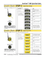
Page 3: ...strial DX80 housing meets IEC IP67 standards Mounting Hole 10 M5 Clearance Mounting Holes accept metric M5 or UNC UNF 10 hardware DIN rail mount adapter bracket available Wiring Terminal Strip Wiring...

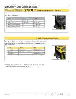
Page 4: ...D SAVESNEW VALUES CUR XX Single click Button 2 Single click Button 2 ADJUSTROTARY SWITCHES TOSET SLAVEID SAVESNEW VALUES NID SLID BAUD PRTY Network ID Slave ID Baud Rate Parity Single click B1 NEW XX...

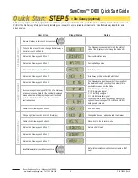
Page 5: ...ouble click Btn 2 NEW XX Single click Button 2 Single click Button 2 SAVESNEW VALUES NADR Node Address NOD XX EC XX IGNORE ERROR Single click Button 1 LCD will display NO ERR if no error is detected S...

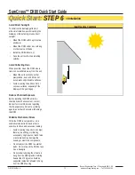
Page 6: ...hexidecimal 0 F On the Gateway set the Right Rotary Switch to 0 A Device Address of 0 on the Gateway will display settings for the Gateway itself To view settings for another device on the network adj...

Page 7: ...e is Gateway Device Address 0 Indicates the current status of the I O The display cycles through each I O point of the device then returns to RUN Apply power This reading occurs only when power is app...

Page 8: ...LED 2 flashes Red When communication is established the Node s LED 1 flashes Green Status LED 1 LED 2 Power ON Green ON System Error Red Flash Red Flash Modbus Communication Active Yellow Flash Modbus...

Page 9: ...ble install all devices in positions that optimize the percentage of YELLOW and GREEN data packets received Examine reception readings M R Y G of the Gateway at various locations Note that the numbers...

Page 10: ...le surfaces Avoid mounting the units on flat or concave surfaces especially if the display will be pointing up Reduce Chemical Exposure Before installing the DX80 units in a chemically harsh environme...

Page 11: ...loosely and Pushed against the flanged cover When removing or closing the rotary switch access cover manually twist the cover into position Do not allow cross threading between the cover and the DX80...

Page 12: ...ically for optimal RF communication If necessary consider changing the height of the DX80 position to improve reception levels A wireless network can be hindered by radio interference and obstructions...

Page 13: ...e o ring when it is damaged discolored or showing signs of wear The o ring should be Seated firmly against the threads without stretching to fit or without bulging loosely and Pushed against the flang...

Page 14: ...of the battery holder mounted within the case After replacing the battery allow up to 60 seconds for the device to power up When removing the battery press the battery towards the negative terminal to...

Page 15: ...shown below The following procedure is necessary to change the Gateway Slave ID Baud Rate and Parity Parameter Description Slave ID Default 1 Defines the slave number 01 99 for the serial Modbus RTU p...

Page 16: ...19200 Single click Gateway push button 2 to save the new setting Single click Gateway push button 1 to move to the next field the PARITY field Single click Gateway push button 2 to display the current...

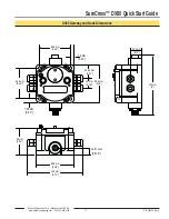
Page 17: ...annerengineering com Tel 763 544 3164 SureCross DX80 Quick Start Guide 17 DX80 Gateway and Node Dimensions 65 0 mm 2 56 65 0 mm 2 56 80 3 mm 3 16 80 8 mm 3 18 60 mm 2 36 120 mm 4 72 127 mm 5 19 mm 0 7...

Page 18: ...f each Node on the network If after a specified number of sequential polling cycles the Node does not acknowledge a message the Gateway considers the link with the Node timed out LCD displays on both...

Page 19: ...devices After any system parameter changes cycle power to cause the devices to resync with the network If a Node device loses synchronization with the network it is programmed to try to acquire sync...

Page 20: ...ling mode within RUN to freeze the I O status on the LCD display for the device in question Verify that when the input device changes state or changes value the LCD mirrors the behavior Also verify th...

Page 21: ...X80 BWA HW 003 Tape PFTE Sealant BWA HW 004 Screws Cover Mount 8 32 x 3 4 18 8 SS Power DX81 Battery Pack Kit DX81 with mounting hardware DX121 Battery Pack Kit DX121 6 cells BWA BATT 001 Replacement...

Page 22: ...rdance with the instructions may cause harmful interference to radio communications However there is no guarantee that interference will not occur in a particular installation If this equipment does c...

Page 23: ...and if not installed and used in accordance with the instructions may cause harmful interference to radio communications However there is no guarantee that interference will not occur in a particular...

Page 24: ...ring the warranty period This warranty does not cover damage or liability for the improper application of Banner products This warranty is in lieu of any other warranty either expressed or implied CAU...

Reviews: