background image

Banner Engineering Corp.

 • Minneapolis, MN U.S.A 

www.bannerengineering.com • Tel: 763.544.3164

2

      P/N 140371 Rev. H 

Sure Cross® Ethernet Data Radio

* There is a limit of 64 routable MAC addresses per access point. This allows an Ethernet switch to be attached to subscriber 

units, but limits to 64 the total number of Ethernet devices to which the access point can connect.

** There is a limit of 16 active subscriber units for each access point. A total of 12 access points (in the 900 MHz band) can be 

deployed to support up to 192 fixed subscriber units across a given site.

Radios are IP addressable*, with remote configuration and diagnostic tools. 

Radios support multiple IP addresses at each remote node.**

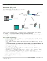
Network Diagram

Ethernet Radio, 

Access point

Ethernet Radio, 

Subscriber unit

Ethernet Radio, 

Subscriber unit

Managed Switch

Set-up Procedures

1.  Starting with all units powered off, select a radio to operate as the access point data radio and set its DIP switch 1 to the 

ON position to enable access point operation.

2.  Apply power to the units.
3. 

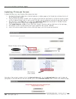
Using the Ethernet cable, connect the access point radio to your computer. Go to 192.168.17.17 to view the configuration 

web pages.

To view the configuration screens, enter the password and click the Login button. The default password is “password.” The 

IP address and default password is printed on a sticker on the radio board instead of the Ethernet radio device. Note that 

configuration changes made using these web-based screens will override any DIP switch settings.

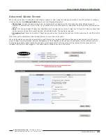
4.  Go to the 

Advanced Admin

 screen.

5.  Select 

Enable User Specified Keys

.

6.  For the access point: Enter the number of subscriber devices connected. For the subscriber units: Assign a unique 

subscriber ID, in numerical order from 1 to 63.

7.  Enter an 8-digit hex (0 to 9 and A through F) network name. Use the hyphens as shown on the screen. Use this same 

network name for the access point (master) and all subscriber units (slaves) in the same network.

8.  Enter a 32-digit encryption key. Use the hyphens as shown on the screen. Use this same encryption key for all radios 

within the same network.

9.  Click 

Apply

 to send the information to the Ethernet data radio.

10.  Repeat steps 2 through 8 for all subscriber units.
11.  Cycle power to all radios to activate the new keys.
12.  Deploy the radios.

PLC

Ethernet Radio, 

Subscriber unit

Plant-wide network

HMI

Remote I/O

HMI

Summary of Contents for Sure Cross DXER9

Page 1: ...connection 900 MHz Overview The Sure Cross Ethernet radio allows the user to create a long range wireless Ethernet network for up to 16 subscriber unit radios for each access point radio The access p...

Page 2: ...cess point radio to your computer Go to 192 168 17 17 to view the configuration web pages To view the configuration screens enter the password and click the Login button The default password is passwo...

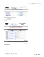
Page 3: ...P N 140371 Rev H 3 Banner Engineering Corp Minneapolis MN U S A www bannerengineering com Tel 763 544 3164 Sure Cross Ethernet Data Radio Login Screen Advanced Admin Screen...

Page 4: ...ng If DIP 1 is accidentally toggled DIP 1 can be returned to its previous position and the radio retains all the network associations it had in its previous mode assuming the radio had not yet success...

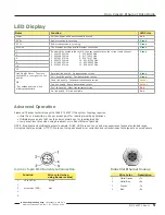
Page 5: ...Ethernet Hookup Wire Color Description 1 White Orange Tx 2 White Blue Rx 3 Orange Tx 4 Blue Rx LED Display Name Function LED Color Power Unit has power and has successfully booted Red RF Rx Radio rec...

Page 6: ...error rate rises the access point data radio autonomously changes to a new channel There are 12 non overlapping channels Manual Frequency Selection Mode The operation of the Sure Cross Ethernet radio...

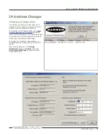
Page 7: ...k when the program is launched To download this IP Address Utility go to www bannerengineering com SureCross and access either the Software page or the Data Radio page The sample screen shown illustra...

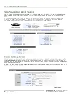
Page 8: ...on a sticker on the radio board instead of the Ethernet radio device Note that configuration changes made using these web based screens will override any DIP switch settings Device Settings Screen Aft...

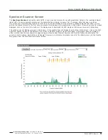
Page 9: ...time you access this web page this graphic may not be visible If there is no graphic images displayed click on the link at the bottom of the display area to download the SVG plugin and follow your br...

Page 10: ...eering s website 2 Using the radio s web browser interface enter the password and click the Login button If you don t know the password use the IP Address Changer utility to read or reset it This file...

Page 11: ...e User Specified Keys and select and enter an 8 digit hex 0 9 and A F Network name that will be common among the Access Point and its Subscriber Units The hyphen is required Encryption key Choose and...

Page 12: ...ating refer to the UL section below Compliance Statement Part 15 9 This device complies with Part 15 of the FCC Rules Operation is subject to the following two conditions this device may not cause har...

Page 13: ...roduct to a country other than that to which it was sold must ensure that the device is approved in the destination country A list of approved countries appears in the Sure Cross DX80 Wireless Product...

Page 14: ...d 7 2 dBi With ground plane N Female Banner offers a range of omni directional and directional Yagi antennas for use with the Sure Cross DX80 wireless network For more information on antenna specifica...

Page 15: ...1MRSFRSB1 RG58 RP SMA to RP SMA Female Bulkhead 1 m BWC 1MRSFRSB2 RG58 RP SMA to RP SMA Female Bulkhead 2 m BWC 1MRSFRSB0 2 RG58 RP SMA to RP SMA Female Bulkhead 0 2 m BWC 4MNFN3 LMR400 N Type Male t...

Page 16: ...ts reserved Banner Engineering Corp warrants its products to be free from defects in material and workmanship for one year following the date of shipment Banner Engineering Corp will repair or replace...

Reviews: