Icon
Description
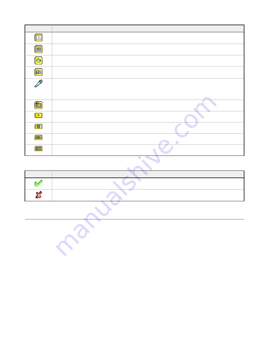
The Hide Annotations icon is one of three icons in the upper-left corner of the display while monitoring
inspections on the Home screen. Click this icon to disable highlighting.
The Show Statistics icon is one of three icons in the upper-left corner of the display while monitoring inspections.
Click this icon to show inspection results and input parameters.
The Go Back icon is located on the lower-left of the display while working in the Main Menu. Click this icon to
return to the previous screen or menu.
The Manual Trigger icon is located on the lower-right of the display on the Home screen. Click this icon to
manually capture a new image.
The Intensity Selector is located on the left of the of the Intensity Range screen. Click this icon to select the
shade of one of the objects of interest.
The Color Selector is located on the left side of the Color screen for the Color Area sensor. Click this icon to
select the color of one of the objects of interest. (Color models only.)
The Add Mask icon is on the left side of the display when masking is enabled. Click this icon to add a mask to
the currently selected sensor.
The Delete Mask icon is on the left side of the display when a mask is selected. Click this icon to delete a mask
from the currently selected sensor.
The Circular Mask icon is on the left side of the display when a mask is selected. Click this icon to cycle through
and select a circular, elliptical, or rectangular-shaped mask.
The Elliptical Mask icon is on the left side of the display when a mask is selected. Click this icon to cycle through
and select a circular, elliptical, or rectangular-shaped mask.
The Rectangular Mask icon is on the left side of the display when a mask is selected. Click this icon to cycle
through and select a circular, elliptical, or rectangular-shaped mask.
Display Icons
Icon
Description
The Inspection Passed icon is located in the upper-left of the display. This icon indicates that the last inspection
passed the test conditions.
One of the possible Inspection Failed icons located in the upper-left of the display. This icon indicates that the
last inspection failed.
Acquiring a Good Image
The iVu needs to capture a good image of each part to ensure that it correctly passes good parts and fails bad parts.
1. Go to Main Menu > Imager > Auto Exposure to run the Auto Exposure routine.
2. Check the lighting.
•
Make sure that the lighting is constant and consistent (unchanging over time, no shadows or hot spots).
•
Capture the shape and form of the target object with lighting that optimizes its contrast and separates it from the
background. Depending on the target, this may mean the integral ring light is not the best choice and other Banner
lights should be considered.
•
Adjust the mounting angle to provide the clearest image of the part features you are monitoring. The mounting
bracket lets you easily position and adjust the iVu.
iVu Plus TG and Color Gen2 Image Sensors
6
www.bannerengineering.com - Tel: +1-763-544-3164
P/N 178442 Rev. C


