background image


Speaker role


Transmitter socket


Left back


PL1 left


Right back


PL1 right


Left front


PL2 left


Right front


PL2 right


Subwoofer


PL3 left and right


C

E

N

T

R

E


1


1

 (SU

B)


2


P

O

W

E

L

IN

K


3


4


5


6


7


PL 5 

PL 4


MONITOR 

CONTROL


Make the wireless connections 


>  Press the SELECT button for the transmitter to 

find the wireless speakers. The transmitter

’s 

wireless status indicator starts flashing green 

and the speakers

’ wireless status indicators 

become solid green for some seconds before 

switching off. A PL status indicator lights up 

– 

red or white 

– for each speaker found.*

1


PL 3 

PL 2 

PL1


PL 1 

PL 2 

PL 3


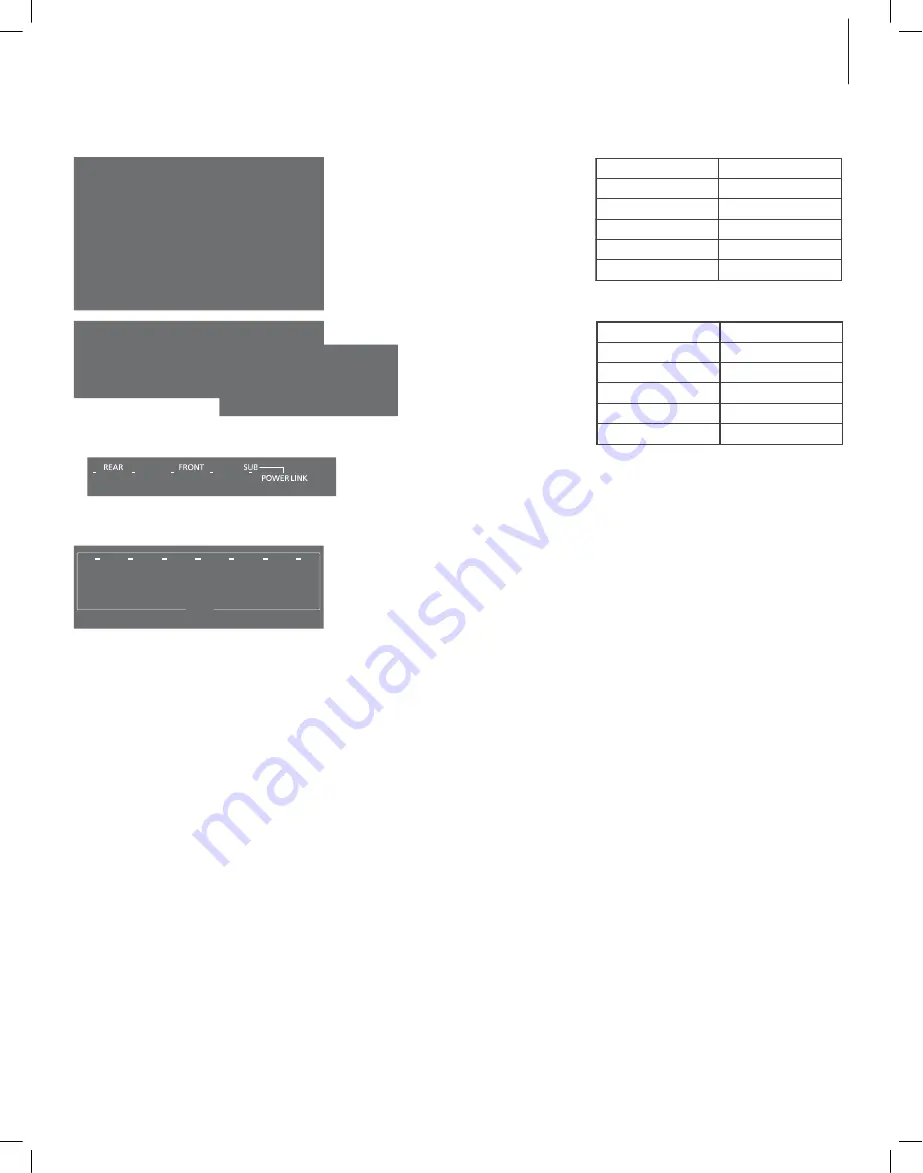
Two examples of Power Link sockets that are not 

predefined.


Example of predefined  Power Link sockets.


Example of Power Link sockets where only the 

subwoofer and centre speaker sockets are 

predefined.


… non-predefined speakers are detected 
automatically:


>  A wireless connection is found automatically 

between the transmitter and each speaker. 

Press the STORE button on the transmitter to 

store the wireless connections. All PL status 

indicators for the connected speakers changes 

to solid light and then switches off.


>  You must now set up the speaker roles and 

types in the television menu. See the guide for 

your television.


… predefined speakers are not detected 
automatically:


>  Press and hold the SELECT button on the 

transmitter for more than 1.5 seconds to be able 

to configure the speakers. The leftmost PL 

status indicator is now flashing, the others are 

switched off, and a sound may be produced in 

one of the speakers.


>  First, you must set up the left speaker 

connected to PL1 on the transmitter, see the 

examples of setups on this page. If the Power 

Link sockets on your television are predefined, 

you must have in mind, which socket on the 

television is connected to which PL socket on 

the transmitter. If sound does not come from 

the intended speaker, press  SELECT once  or


repeatedly until sound comes from the intended 

speaker, then press the STORE button on the 

transmitter. The leftmost PL status indicator 

becomes solid and the next PL status indicator 

starts flashing. A sound may be produced in 

another speaker.


>  Repeat the previous step for all speakers in your 

setup. When the last PL status indicator starts 

flashing, it will automatically become solid after 

a while and the wireless connection has now 

completed.


Example of a setup with all speakers predefined.


Speaker role


Transmitter socket


Left front


PL1 left


Right front


PL1 right


Left back


PL2 left


Right back


PL2 right


Subwoofer


PL3 left and right


Example of a setup where only the subwoofer is 

predefined.


>  When you have made a wireless connection to 

all speakers, all PL status indicators for the 

connected speakers changes to solid light and 

then switches off. You must now enter your 

television menu and set up speaker types if all 

the Power Link sockets on the television are 

predefined or speaker roles if only the centre 

and subwoofer sockets on the television are 

predefined.*

2  

See the guide for your television.


1

*If all speakers are not found, make sure that they 

are flashing green to be searchable. If this is not 

the case, see the guide enclosed with your 

speakers to reset them. Then press the SELECT 

button to find the wireless speakers.


2

*When you set up the speaker distance in the 

television menu, we recommend that you subtract


1.7 metres (20 ms.) from the actual distance for 

each wireless speaker due to a sound delay.


During setup, if you inadvertently store a wrong 

speaker on a left or right PL input, you can shortly 

press the SELECT and  STORE buttons 

simultaneously to go back one step and 

reconfigure the left or right PL input just 

configured.


Summary of Contents for Beolab transmitter 1

Page 1: ...Beolab Transmitter 1 BANG OLUFSEN...

Page 2: ...se of the polarized or grounding type plug A polarized plug has two blades with one wider than the other A grounding type plug has two blades and a third grounding prong The wide blade or the third pr...

Page 3: ...contiene esta gu a est destinada principalmente al distribuidor Le informazioni contenute in questa Guida sono primariamente indirizzate al rivenditore As informa es inclu das neste Livro de consulta...

Page 4: ...onnection of an audio system The volume of the signal should be adjusted on the non Bang Olufsen product SUB 2 1 OFF ON Subwoofer switch ON is for connection of a 2 1 setup with an audio system 2 spea...

Page 5: ...t the transmitter see www bang olufsen com To obtain the best possible wireless connection it is recommended to place all speakers within a distance of approximately 9 metres 29 5 ft from the transmit...

Page 6: ...e PL sockets from the left PL1 to the right Four Power Link cables are shown here which is a full 7 1 setup If you have more speakers or a subwoofer to connect connect one end of a Power Link cable to...

Page 7: ...socket on the television is connected to which PL socket on the transmitter If sound does not come from the intended speaker press SELECT once or repeatedly until sound comes from the intended speake...

Page 8: ...ators become solid green for some seconds before switching off A PL status indicator lights up red or white for each speaker found 1 Press and hold the SELECT button on the transmitter for more than 1...

Page 9: ...id after a while and the wireless connection has now completed When you have made a wireless connection to Examples comparing an all wireless setup and a setup with wired front speakers Fill up the PL...

Page 10: ...re og venstre lydindgang til tilslutning af et musiksystem Signalets lydstyrke b r justeres p selve produktet SUB 2 1 OFF ON Subwoofer omskifter ON bruges i en 2 1 ops tning med et musiksystem to h jt...

Page 11: ...ng Olufsen anbefaler at skrive navnet ned p de stik der er tilsluttede mellem BeoLab Transmitter 1 senderen og A V produktet Se www bang olufsen dk for oplysninger om BeoLab Transmitter 1 Fjern alle g...

Page 12: ...alle Power Link stikkene i fra venstre PL 1 til h jre Her vises fire Power Link stik dvs en komplet 7 1 ops tning Hvis du har flere h jttalere eller en subwoofer skal du tilslutte dem ved at s tte de...

Page 13: ...r du notere de forbundne stik p hhv tv og sender Hvis den p g ldende h jttaler ikke afgiver en lyd skal du trykke p SELECT en eller gentagne gange indtil du h rer en lyd Tryk derefter p knappen STORE...

Page 14: ...jttalere Opret tr dl s forbindelse Tryk p knappen SELECT p senderen for at registrere de tr dl se h jttalere Senderens tr dl s forbindelse diode begynder at blinke gr nt og h jttalernes tr dl s forbin...

Page 15: ...giver muligvis en lyd Gentag foreg ende trin for alle h jttalerne i din ops tning N r den sidste PL statusdiode begynder at blinke begynder den automatisk at lyse konstant efter nogle sekunder Alle tr...

Page 16: ...ingestellt werden INPUT R L Linker und rechter Line Eingang f r den Anschluss eines Audiosystems Die Lautst rke des Signals sollte an dem nicht von Bang Olufsen stammenden Produkt eingestellt werden S...

Page 17: ...schen den Funklautsprechern und dem Sender sollte eine Sichtverbindung bestehen In Abh ngigkeit von der Art des verwendeten TV Ger ts kann die Vorgehensweise beim Anschlie en der Kabel und bei der Wir...

Page 18: ...der vorzunehmenden Verbindungen Belegen Sie die PL Buchsen von links PL1 nach rechts Hier werden vier Power Link Kabel verwendet was einer vollst ndigen 7 1 Konfiguration entspricht Wenn im Anschluss...

Page 19: ...cken Sie die Taste SELECT einmal oder mehrmals bis der korrekte Lautsprecher ert nt Dr cken Sie dann die Taste STORE am Sender Die u ere linke PL Statusanzeige leuchtet dauerhaft und die n chste PL S...

Page 20: ...eginnt gr n zu blinken Die Wireless Statusanzeigen der Lautsprecher leuchten einige Sekunden lang gr n und erl schen dann F r jeden gefundenen Lautsprecher leuchtet eine PL Statusanzeige auf entweder...

Page 21: ...Senders von links PL1 nach rechts wobei der Subwoofer als letztes verbunden wird sofern er kabellos ist Die kabelgebundenen Lautsprecher werden automatisch konfiguriert Die verbleibenden kabellosen L...

Page 22: ...luiting op een audiosysteem Op een product van een ander merk dan Bang Olufsen moet de signaalsterkte worden aangepast SUB 2 1 OFF ON Schakelaar subwoofer ON is voor de aansluiting van een 2 1 opstell...

Page 23: ...vindt u op www bang olufsen com Het is aanbevolen om alle luidsprekers op een afstand van ongeveer 9 meter van de zender te plaatsen om de beste draadloze verbinding te hebben Plaats geen voorwerpen v...

Page 24: ...w televisie op deze pagina Plug de PL aansluitingen in van links PL1 naar rechts Hier worden vier Power Link kabels weergegeven in een volledige 7 1 opstelling Als u meer luidsprekers of een subwoofer...

Page 25: ...ls er geen geluid komt uit de bedoelde luidspreker druk dan een of verschillende keren op SELECT totdat er geluid komt uit de bedoelde luidspreker Druk dan op STORE op de zender De PL statusindicator...

Page 26: ...uitingen Druk op de SELECT knop voor de zender om de draadloze luidsprekers te vinden De draadloze statusindicator van de zender begint groen te knipperen en de draadloze statusindicatoren van de luid...

Page 27: ...en de draadloze aansluiting is nu voltooid Van zodra u de draadloze aansluiting hebt Vergelijkend voorbeeld tussen een draadloze opstelling en een opstelling met bekabelde luidsprekers voor Plug de P...

Page 28: ...yst me audio Le volume du signal doit tre ajust sur l appareil d une marque autre que Bang Olufsen SUB 2 1 OFF ON Commutateur du subwoofer ON correspond la connexion d un syst me audio en configuratio...

Page 29: ...r le site www bang olufsen com Pour b n ficier de la meilleure connexion sans fil possible nous vous recommandons de placer toutes les enceintes une distance d environ 9 m tres par rapport l metteur V...

Page 30: ...PL1 vers la droite Quatre c bles Power Link sont pr sent s ici ce qui correspond une configuration compl te 7 1 Si vous avez d autres enceintes ou un subwoofer installer branchez l extr mit d un c bl...

Page 31: ...hait e n met aucun son appuyez une ou plusieurs fois sur SELECT jusqu ce qu un son soit mis puis appuyez sur le bouton STORE de l metteur L indicateur d tat PL le plus gauche s allume fixe et le suiva...

Page 32: ...bouton SELECT de l metteur pour d tecter les enceintes sans fil L indicateur d tat de la connexion sans fil de l metteur se met clignoter en vert et celui de l enceinte s allume en vert fixe pendant...

Page 33: ...une configuration enti rement sans fil et une configuration avec enceintes avant filaires Branchez les l ments sur les prises PL de l metteur en allant de la gauche PL1 vers la droite en connectant l...

Page 34: ...los canales izquierdo y derecho de un sistema de audio El volumen de la se al deber ajustarse a trav s del equipo del otro fabricante SUB 2 1 OFF ON Interruptor de subwoofer coloque este interruptor...

Page 35: ...com si desea obtener m s informaci n acerca del transmisor Para que la conexi n inal mbrica tenga lugar de la mejor forma posible se recomienda situar todos los altavoces a una distancia inferior a 9...

Page 36: ...n las tomas PL de izquierda PL 1 a derecha Esta ilustraci n muestra cuatro cables Power Link que permitir an crear una instalaci n 7 1 completa Si a n queda alg n altavoz o subwoofer por conectar cone...

Page 37: ...da a qu toma PL del transmisor Si el sonido no se reproduce a trav s del altavoz esperado pulse el bot n SELECT una o m s veces hasta que as sea pulse entonces el bot n STORE del transmisor El indicad...

Page 38: ...s inal mbricos El indicador de estado de la conexi n inal mbrica del transmisor comenzar a parpadear en color verde y los indicadores de estado de la conexi n inal mbrica de los altavoces se iluminar...

Page 39: ...mo lugar si forma parte de la instalaci n y su conexi n debe tener lugar de forma inal mbrica Los altavoces con conexi n por cable se configurar n autom ticamente por lo que el resto de conexiones cor...

Page 40: ...resso di linea sinistro e destro per il collegamento di un impianto audio Il volume del segnale deve essere regolato sul prodotto di altra marca SUB 2 1 OFF ON Interruttore subwoofer ON per il collega...

Page 41: ...no essere collocati in una stanza e tutti i diffusori wireless devono essere visibili dal trasmettitore A seconda del tipo di televisore nella propria configurazione la procedura di configurazione del...

Page 42: ...nti alle prese PL da sinistra PL1 verso destra Qui sono illustrati quattro cavi Power Link vale a dire una configurazione 7 1 completa Se si devono collegare altri diffusori e un subwoofer inserire un...

Page 43: ...Se il diffusore selezionato non emette un segnale acustico premere SELECT una volta o pi volte fino a quando il segnale acustico non viene emesso dal diffusore selezionato quindi premere il pulsante...

Page 44: ...ome effettuare le connessioni wireless Premere il pulsante SELECT sul trasmettitore in modo che rilevi i diffusori wireless L indicatore di stato wireless inizia a lampeggiare in verde e gli indicator...

Page 45: ...stato PL lampeggiante si illumina costantemente dopo un certo periodo di tempo la connessione Confronto fra una configurazione completamente wireless e una con diffusori frontali cablati Effettuare i...

Page 46: ...ra liga o de um sistema udio O volume do sinal deve ser ajustado no aparelho n o Bang Olufsen SUB 2 1 OFF ON Interruptor do subwoofer ON serve para ligar uma configura o 2 1 com um sistema udio 2 colu...

Page 47: ...unas devem ser colocadas na mesma sala e todas as colunas sem fios devem ser vis veis a partir do transmissor Consoante o tipo de televisor presente na sua instala o a liga o de cabos e o procedimento...

Page 48: ...ina Preencha os terminais PL da esquerda PL1 para a direita S o aqui apresentados quatro cabos Power Link pertencente a uma instala o completa 7 1 Se tiver mais colunas ou um subwoofer para ligar ligu...

Page 49: ...ligado a qual terminal PL do transmissor Se n o for emitido som da coluna pretendida prima SELECT uma vez ou repetidamente at ser emitido som da coluna pretendida e depois prima o bot o STORE no trans...

Page 50: ...ar as liga es sem fios Prima o bot o SELECT do transmissor para detectar as colunas sem fios O indicador de estado da liga o sem fios do transmissor pisca a verde e os indicadores de estado da liga o...

Page 51: ...st conclu da Exemplos de compara o de uma instala o totalmente sem fios e uma instala o com colunas dianteiras com fios Preencha os terminais PL do seu transmissor da esquerda PL1 para a direita ligan...

Page 52: ...STORE PL USB B USB A USB www bang olufsen com PL1 4 PL B O INPUT NO YES YES Bang Olufsen NO Bang Olufsen TOSLINK ToslinkTM Bang Olufsen INPUT R L Bang Olufsen SUB 2 1 OFF ON ON 2 1 2 1 OFF PL1 TOSLINK...

Page 53: ...53 Bang Olufsen 9 Bang Olufsen TosLink 30 www bang olufsen com SELECT STORE 1 5...

Page 54: ...e e e e Power Link PL1 Power Link Power Link Power Link PL2 Power Link Power Link Power Link PL3 Power Link Power Link PL PL1 Power Link 7 1 Power Link PL4 Power Link Power Link Power Link PL Left REA...

Page 55: ...NK 3 4 5 6 55 PL 5 PL 4 MONITOR CONTROL SELECT PL 3 PL 2 PL1 PL 1 PL 2 PL 3 Power Link Power Link Power Link PL 1 STORE PL SELECT 1 5 PL PL1 Power Link PL SELECT STORE PL PL PL PL1 left PL1 right PL2...

Page 56: ...L2 right PL3 left PL3 right PL4 left PL4 right 56 Bang Olufsen PL PL1 Power Link Bang Olufsen e e e e e PL1 PL2 PL3 Power Link PL4 SELECT PL 1 SELECT 1 5 PL 2 PL1 SELECT STORE PL PL PL PL 3 7 1 PL SEL...

Page 57: ...t PL1 right 2 1 SUB 2 1 ON PL PL2 left PL2 right Power Link PL1 1 Power Link PL2 SELECT STORE PL1 left PL1 right PL PL PL PL PL1 1 7 SELECT PL 2 SELECT 1 5 PL PL 1 Bang Olufsen INPUT R L TOSLINK 2 SEL...

Page 58: ...STORE PL USB B USB A USB www bang olufsen com PL1 4 PL B O INPUT NO YES YES Bang Olufsen NO Bang Olufsen TOSLINK ToslinkTM Bang Olufsen INPUT R L Bang Olufsen SUB 2 1 OFF ON ON 2 1 Bang Olufsen 2 1 OF...

Page 59: ...59 Bang Olufsen Bang Olufsen 9m Bang Olufsen TosLink 30mm www bang olufsen com SELECT STORE 1 5...

Page 60: ...r Link PL 3 PL 2 PL1 PUC 3 A B CTRL 3 PL1 PL 2 Power Link PL2 Power Link Power Link 2 Power Link PL Power Link Power Link Power Link Power Link 4 7 1 PL4 Power Link Power Link Power Link Power Link PL...

Page 61: ...4 5 6 61 PL 5 PL 4 MONITOR CONTROL SELECT PL 1 PL 3 PL 2 PL1 PL 1 PL 2 PL 3 Power Link 2 Power Link Power Link STORE PL SELECT 1 5 PL PL1 Power Link PL SELECT STORE PL PL PL PL1 PL1 PL2 PL2 PL3 PL Po...

Page 62: ...1 PL2 PL2 PL3 PL3 PL4 PL4 62 Bang Olufsen PL PL1 Power Link Bang Olufsen PL1 2 PL2 2 PL3 2 PL4 Power Link 2 SELECT PL 1 SELECT 1 5 PL 2 PL1 SELECT STORE PL PL PL PL 3 7 1 PL SELECT STORE PL 1 SELECT 2...

Page 63: ...Olufsen 2 1 SUB 2 1 3 PL PL1 PL2 PL1 PL1 PL2 PL1 PL1 Power Link 1 PL2 Power Link SELECT STORE PL PL PL PL SELECT 1 INPUT R L TOSLINK Bang Olufsen PL PL1 1 7m PL 2 SELECT 1 5 PL 2 SELECT PL SE L E C T...

Page 64: ...Hz WIRELESS SELECT STORE PL USB B USB A USB www bang olufsen com PL1 4 PL B O INPUT NO YES YES Bang Olufsen NO TOSLINK ToslinkTM INPUT R L SUB 2 1 OFF ON ON 2 1 2 1 OFF PL1 TOSLINK INPUT R L Bang Oluf...

Page 65: ...65 Bang Olufsen Bang Olufsen TosLink 30 mm 1 18 9 m 29 5 ft TV www bang olufsen com SELECT STORE 1 5...

Page 66: ...Link PL2 TV Power Link TV Power Link Power Link PL3 TV Power Link TV Power Link PL PL1 7 1 Power Link Power Link PL4 TV Power Link TV Power Link TV PL 3 PL 2 PL1 PUC 3 A B CTRL 3 TV TV Power Link PL...

Page 67: ...MONITOR CONTROL SELECT PL 1 PL 3 PL 2 PL1 PL 1 PL 2 PL 3 Power Link Power Link Power Link STORE PL TV TV SELECT 1 5 PL PL1 TV Power Link TV PL SELECT STORE PL PL PL Left front PL1 Right front PL1 Left...

Page 68: ...wer Link PL4 SELECT PL 1 SELECT 1 5 PL 2 PL1 SELECT STORE PL PL PL PL TV 3 TV PL1 Left front PL1 Right front PL2 Left surround PL2 Right surround PL3 Left back PL3 Right back PL4 PL4 7 1 PL SELECT STO...

Page 69: ...2 1 ON PL PL1 PL2 PL2 PL1 Power Link PL1 1 Power Link PL2 SELECT STORE PL PL Left front PL1 Right front PL1 SELECT PL PL PL PL1 TV Sound Delay 1 7 m 20 ms PL 2 SELECT 1 5 PL 1 INPUT R L TOSLINK 2 SEL...

Page 70: ...CT STORE PL USB B USB A USB www bang olufsen com PL1 4 PL B O NO YES YES Bang Olufsen NO Bang Olufsen TOSLINK ToslinkTM Bang Olufsen INPUT R L Bang Olufsen SUB 2 1 OFF ON ON 2 1 2 1 OFF PL1 TOSLINK IN...

Page 71: ...71 Bang Olufsen Bang Olufsen Bang Olufsen TosLink 30 1 18 www bang olufsen com 9 29 5 SELECT STORE 1 5...

Page 72: ...ower Link Power Link PL2 Power Link Power Link Power Link PL3 Power Link Power Link PL1 PL 7 1 4 Power Link Power Link PL4 Power Link Power Link MONITOR PUC 2 PL 5 PL 4 CONTROL A B PL 3 PL 2 PL1 PUC 3...

Page 73: ...1 SUB 2 POWER LINK 3 4 5 6 73 PL 5 PL 4 MONITOR CONTROL SELECT PL 1 PL 3 PL 2 PL1 PL 1 PL 2 PL 3 STORE PL Power Link Power Link Power Link SELECT 1 5 PL PL1 Power Link PL SELECT STORE PL PL PL PL Pow...

Page 74: ...L1 PL2 PL2 PL3 PL3 PL4 PL4 74 Bang Olufsen PL1 PL Power Link Bang Olufsen PL1 PL2 PL3 Power Link PL4 SELECT PL 1 SELECT 1 5 PL 2 PL1 SELECT STORE PL PL PL PL 3 7 1 PL SELECT STORE PL 1 SELECT 2 3 1 7...

Page 75: ...lufsen 2 1 SUB 2 1 ON PL PL1 PL2 PL2 PL1 Power Link PL1 1 Power Link PL2 SELECT STORE PL PL SELECT PL PL PL PL1 PL1 2 SELECT 1 5 PL 1 INPUT R L TOSLINK Bang Olufsen PL1 PL 1 7 20 ms 2 SELECT PL SELECT...

Page 76: ...ORE PL USB B USB A PL1 4 PL B O INPUT B O NO YES YES Bang Olufsen NO Bang Olufsen TOSLINK ToslinkTM Bang Olufsen INPUT R L Bang Olufsen SUB 2 1 OFF ON ON 2 1 2 Bang Olufsen USB www bang olufsen com 1...

Page 77: ...77 Bang Olufsen Bang Olufsen Bang Olufsen TosLink 30 1 18 29 5 www bang olufsen com SELECT STORE 1 5...

Page 78: ...wer Link MONITOR PUC 2 PL 5 PL 4 CONTROL A B PL 3 PL 2 PL1 PUC 3 A B CTRL 3 Power Link PL2 Power Link Power Link Power Link PL3 Power Link Power Link PL1 PL Power Link 7 1 Power Link PL4 Power Link Po...

Page 79: ...3 4 5 6 79 PL 5 PL 4 MONITOR CONTROL SELECT PL 1 PL 3 PL 2 PL1 PL 1 PL 2 PL 3 Power Link Power Link Power Link STORE PL SELECT 1 5 PL PL1 Power Link PL SELECT STORE PL PL PL PL1 PL1 PL2 PL2 PL3 PL Pow...

Page 80: ...L1 PL2 PL2 PL3 PL3 PL4 PL4 80 Bang Olufsen PL PL1 Power Link Bang Olufsen Power Link PL1 PL2 PL3 PL4 SELECT PL 1 SELECT 1 5 PL 2 PL1 SELECT STORE PL PL PL PL 3 7 1 PL SELECT STORE PL 1 SELECT 2 3 1 7...

Page 81: ...g Olufsen 2 1 SUB 2 1 ON PL PL1 PL2 PL2 PL1 Power Link PL1 1 Power Link PL2 SELECT STORE PL PL SELECT PL PL1 PL1 PL 2 SELECT 1 5 PL PL 1 R L TOSLINK Bang PL PL1 1 7 20 ms Olufsen 2 SELECT PL SELECT ST...

Page 82: ...Pb Hg Cd Cr VI PBB PBDE PCBA o o o o o o o o o o o ST T 11363 2006 MCV SJ T 11363 2006 V Hz 00 240 VAC 50 60 Hz 16 0 5 310 x 167 x 33 0 75 www bang olufsen com guides important_information...

Page 83: ...Transmissor de RF modelo 444 2216...

Reviews: