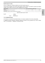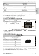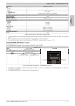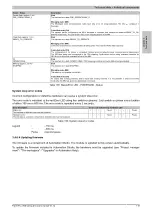
Technical data • Individual components
Chapter 2
Technical data
Panel PC 2100 swing arm user's manual V1.12
117
Extension
Transfer rate
≤1000 m
Typ. 50 kbit/s
≤200 m
Typ. 250 kbit/s
≤100 m
Typ. 500 kbit/s
<20 m
1)
Typ. 1 Mbit/s
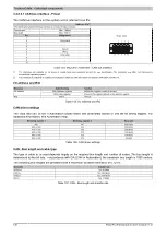
Table 129: CAN - Bus length and transfer rate
1)
The specified cable length is only valid with the values specified in
. Cable lengths additionally depend on the values in the
timing register.
The material used for the cable should have all or most of the following properties in order to achieve an optimal
transfer rate.
CAN cable
Property
Signal lines
Cable cross section
Wire insulation
Conductor resistance
Stranding
Shield
2x 0.25 mm² (24 AWG / 19), tinned copper stranded wire
PE
≤82 Ω/ km
Wires stranded in pairs
Paired shield with aluminum foil
Grounding line
Cable cross section
Wire insulation
Conductor resistance
1x 0.34 mm² (22 AWG / 19), tinned copper stranded wire
PE
≤59 Ω/km
Outer sheathing
Material
Features
Complete shielding
PUR mixture
Halogen-free
From tinned copper wires
Table 130: CAN cable requirements
Terminating resistor
A terminating resistor is integrated in the interface option above the ETH1 interface. A switch is used to enable
or disable the terminating resistor for the CAN bus interface. The L1 LED status indicator indicates whether the
terminating resistor is enabled or disabled.
Terminating resistor
On
The terminating resistor is enabled.
Off
The terminating resistor is disabled.
Table 131: Terminating resistor
3.4.6.3.4 Shielding
For the interfaces on the 10-pin female connector, the interface shield can be put on pin 2 of the female connector.
A functional ground connection, which can also be used for the cable shields, is located on the interface plate of
the system unit.
3.4.6.3.5 LED status indicators - L1, L2, L3
The interface option has 3 integrated LEDs located above the terminating resistor.
LED status indicators
LED
Color
Status
Function
On
CAN bus terminating resistor enabled
L1
Yellow
Off
CAN bus terminating resistor disabled
On
POWERLINK Link LED
Indicates a connection to a POWERLINK net-
work
L2
Green
Blinking
POWERLINK Link LED
Data transfer in progress
On
POWERLINK Status/Error LED
See
L3
Green-Red
Off
POWERLINK Status/Error LED
See
Table 132: 5ACCIF01.FPSC-000 - LED status indicators
Status/Error LED
The Status/Error LED is a green and red dual LED. The LED status can have different meanings depending on
the operating mode.

