Bandit
67
Copyright 12/17
MODEL 18XP/1590
PROPER PROCEDURE FOR INSTALLATION AND REMOVAL
OF J.B. COUPLERS AND TAPERED FEEDWHEEL MOTORS
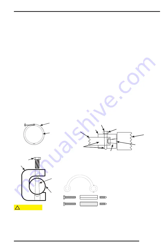
Press Tool for Coupler Pin Removal
Part Number: 981-0501-61
Removal if tapered pin is equipped with a nut to assist in pin removal:
Use a hand wrench and turn the tapered pin nut clockwise, half a turn
and then hit the small end of the tapered pin with a hammer and punch.
Repeat this process until pin is removed.
Always wear proper safety equipment and take caution with tapered pin when attempting to
remove. The use of this tool will assist in the removal of the tapered pin in the feedwheel coupler. Lubricate end of bolt and
threads with grease. Position the press tool so that it cradles the coupler, with the large end of the tapered pin at the side
opposite the press bolt. You may want to remove yoke springs to get easier access to coupler. Set the tool as described
and hand tighten press bolt to snug tool against coupler. Make sure press bolt is set on small end of tapered pin, and that
pin will go through hole in tool without interference. Use of a 1/2” impact wrench is recommended. Run impact on bolt
to start pin removal, then usually a good hit with hammer on the end of bolt will knock out the pin. You may have to run
impact on bolt and hit with hammer a few times to remove pin. Do not spend excessive time trying to remove the pin and
coupler. If problems occur during pin and coupler removal, contact your nearest dealer or Bandit Industries.
CAUTION
!
B.
Installation Procedure
1. Remove any sharp edges on the coupler bores
or the motor shaft. Example: Emery cloth or fi le
for burrs on keyways or shafts.
2. Clean the coupler bores and motor shaft with a
degreasing solvent.
3. Install the correct key in the feedwheel motor shaft.
4. Slide the coupler onto the motor shaft, making
sure that the two mate tightly. Example: The
coupler does not rock or slop on the shaft.
5. Install the self locking nut with Loctite 263 on the
threads.
6. Tighten to the correct torque, 340 ft.-lbs. (461 Nm)
for “DT” motor, 250-300 ft.-lbs. (339-407 Nm) for
“RE/TG” motor, & 150-170 ft.-lbs. (203-230 Nm)
for “RS/TE” motor.
7. Slightly tap with a hammer on the coupler face to
ensure proper seating.
8. Retorque self locking nut.
9. Deburr and degrease the feedwheel shaft.
10. Install the motor and coupler assembly onto the
feedwheel shaft.
11. Install the correct tapered pin through the coupler
and feedwheel shaft.
12. If coupler pin is threaded and is equipped with
a nut, make sure the nut is fl ush with top of pin.
13. Hammer the pin into the coupler to secure the
coupler and feedwheel shaft. If the pin is threaded
and has a nut do not hammer the pin directly, use
a piece of wood as a buff er.
14. If the tapered pin is equipped with a nut, put
Loctite 243 on the threads and then tighten nut
fl ush with top of pin.
A.
Proper Equipment Needed
1. Feedwheel motor with tapered shaft.
2. 5/16” x 9/32” x 1 1/4” long key (900-3937-23) for
“DT” motor.
5/16” x 9/32” x 15/16” long key (900-3934-06)
for “RE/TG” motor.
3/16” x 3/16” x 3/4” long key (900-3937-03) for
“RS/TE” motor.
3. Correct feedwheel shaft, coupler and taper ass’y
4. Loctite 263 (red).
5. Loctite 243 (blue).
6.
Emery cloth and/or a fi le.
7. A degreaser agent.
8. Self locking nut.
9. Hammer.
10. Torque wrench and 1 5/8” socket for “DT” motor.
1 3/8” socket for “RE/TG” motor.
1 3/16” socket for “RS/TE” motor.
11. 1 1/16” hand wrench for “RE/TG” motor
7/8” hand wrench for “RS/TE” motor
Coupler Removal Tool Kit
Part Number: 980-2003-59
COUPLER
PIN
COUPLER
PRESS
TOOL
PRESS
BOLT
1/16” (1.6 mm)
TO
1/8” (3.2 mm)
COUPLER
RUBBER
COUPLER
GUARD
TORQUE AND THREAD SELF LOCKING NUT WITH LOCTITE 263
“DT” MOTOR = 340 FT-LBS (461 Nm) TORQUE
“RE/TG” MOTOR = 250 - 300 FT-LBS (339 - 407 Nm) TORQUE
“RS/TE” MOTOR = 150 - 170 FT-LBS (203 - 230 Nm) TORQUE
NO LOCTITE
BUT SURFACE
CLEAN AND DRY
NO LOCTITE
BUT SURFACE
CLEAN AND DRY
IF EQUIPPED, LOCTITE 243 AND
TIGHTEN NUT FLUSH WITH TOP OF PIN
HAMMER FIT TAPER PIN SECURE IN PLACE
COUPLER
FEEDWHEEL
SHAFT
HYDRAULIC
MOTOR
MAINTENANCE


