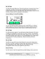
10
Chapter 2
Documentation Number: ESP902-2303 Manual
B&B Electronics Mfg Co Inc – 707 Dayton Rd - PO Box 1040 - Ottawa IL 61350 - Ph 815-433-5100 - Fax 815-433-5104
B&B Electronics Ltd – Westlink Commercial Park – Oranmore, Galway, Ireland – Ph +353 91-792444 – Fax +353 91-792445
Upgrade Mode
You can install newly revised firmware for the ESP902 using RS-232
connections from a PC, through the ESP Manager or through the Virtual COM
port. See Chapter 8 for details.
Console Mode
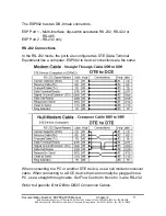
The Console mode provides access to the configuration menu using RS-232
connections. Connect a null modem crossover cable between the multi-
interface port and one of the computer’s RS-232 serial ports. The ESP902
Serial ports are wired as DTE like a computer using DB9M connectors, so a
crossover cable must be used to connect to another DTE port.
In Console mode the default serial port settings are: 9600 baud, 8 data bits,
No parity, and 1 stop bit. With Windows, you can use HyperTerminal with
VT100 terminal emulation for Console mode configuration. Use the default
settings only if they have not been changed. See Chapter 7 for details.
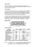
Bottom View
Serial Connections
RS-232
Signal Name
DTE
RS-232 DB9M
Pin
RS-422 RS-485
Carrier Detect
In
DCD
1
RXDA (
−
) --
Receive (Rx) Data
In
RXD
2
RXDB (+)
--
Transmit (Tx) Data
Out
TXD
3
TXDB (+) Data B (+)
DataTerminal
Ready
Out
DTR
4
TXDA (
−
)
Data A (
−
)
Signal Ground
---
GND 5 GND GND
Data Set Ready
In
DSR
6
CTSA (
−
) --
Request To Send
Out
RTS
7
CTSB (+) --
Clear To Send
In
CTS
8
RTSB (+) --
Ring Indicator
In
RI
9
RTSA (
−
)
Table 2.3 - Serial Connection Pin-outs for RS-232/RS-422/RS-485

