4
Chapter 1
Documentation Number: ESP902-2303 Manual
B&B Electronics Mfg Co Inc – 707 Dayton Rd - PO Box 1040 - Ottawa IL 61350 - Ph 815-433-5100 - Fax 815-433-5104
B&B Electronics Ltd – Westlink Commercial Park – Oranmore, Galway, Ireland – Ph +353 91-792444 – Fax +353 91-792445
Step 1: Decide which method to use for configuration and operation.
If using the Console mode for setup, refer to the Console mode
section, Chapter 9, and Chapter 5, then power up the unit.
Step 2: Attach the ESP902 to your network or computer Ethernet port. You
can connect your serial devices now if needed.
If using Telnet for setup, refer to the Console mode section, Chapter
9, and Chapter 5, then power up the unit.
Step 3: Install the VLINX ESP Manger software on the configuring Computer
Step 4: Power on the ESP902 and check the status lights.
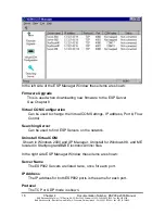
Step 5: Start the VLINX ESP Manager from your program menu.
Step 6: Select
Search
to find the ESP902 on your network.
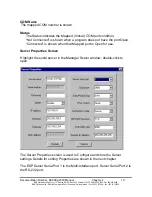
Step 7: When found, Double-Click the ESP902 to bring up the Server
Properties Configuration Screen. If more than one ESP902 shows up,
select the one that matches the Default IP Address shown on the
bottom of the ESP902. (Initially usually IP:902.168.0.1)
Step 8: Refer to the Server Properties section, Chapter 5 for details on the
Configuration parameters for each field. Configure and Save/Update.
Step 9: If you want to use Virtual COM ports with Windows, install the Virtual
COM Port or Ports on each computer requiring access.
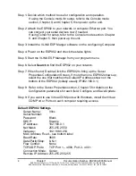
Default ESP902 Settings
Server Name:
Vlinx
Serial Number:
Password:
Blank
DHCP:
Disable
IP Address:
192.168.0.1
Net Mask:
255.255.255.0
Gateway:
192.168.0.254
MAC Address Fixed – see bottom label
Baud Rate:
9600
Data/Parity/Stop: 8-N-1
Flow Control:
None
TCP/UDP Ports:
TCP Port 1 – 4000, Port 2 - 4001
Connection Mode: Server
Remote IP Address: 255.255.255.255

