RS-422/ 485 Connections/Operation
Manual Documentation Number 3PCIoUx-1008
Chapter 8
65
2-Wire RS-485 Connections
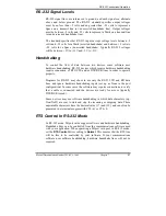
The following diagram shows how to wire the DB-9 connector that will plug
into your MIport card for 2-wire RS-485 operation.
Figure 49. 2-Wire RS-485 Connections
2-Wire RS-485 Mode:
Your cables must bridge pins #1 & #3 and pins #2 & #9 in order to receive
and transmit. Connect from Pin #2 to Data B(
+
) of your devices and from pin
#3 to Data A(-) of your devices. Make sure your DIP switches are set, and
that the driver Setting for RTS Control is
RS-485 Mode
in the Device
Manager, Port Settings, Advanced.
Note that the EIA RS-422 Specification labels data lines with an "A" and "B"
designator. Some RS-422 or RS-485 equipment uses a "
−
" and "+"
designator. In most cases, the "A" line is the equivalent of the "
−
" line and
the "B" line is the equivalent of the "+" line. Some device manufacturers may
not follow the standard designation for RS-422 or RS-485, using the A
connection for “+” and the B for “-“. In such cases, reversing the line pair
permits operation.
4-Wire RS-422 and RS-485 Connections
RS-422 Point to Point Connection
For RS-422 point to point communications connect the MIport card and to
one RS-422 device only.
1.
Connect the TD(B) pin #2 on the computer to RD(B) on the device.
2.
Connect the TD(A) pin #3 on the computer to RD(A) on the device.


