


7 / 71
0006081041_200708
therefore best to stop the
burner immediately after the
twometer readings.
13) Subsequently, with the burner
at maximum supply required by
the boiler, check the combu
stion with the special instruments
and if necessary change the
adjustment previously carried
out (air and possibly gas) with just
the visual check (CO2 max. = 10
% O2 min =3% - CO max. = 0.1%
14) The air pressure switch is there
to prevent the opening of the gas
valves if the air pressure is
not that required. The pressure
switch must therefore be adjusted
to intervene to close
its contact when the air pressu re
in the burner reaches a sufficient
value. The pressure switch con
nection circuit provides for
auto control so it necessary for
the contact to be actually
closed when the fan is
stopped (no air pressure
in burner). If it is not the
command and control equip
ment will not go on (the burner
stays stopped). If the air pressure
switch does not detect
pressure greater than that
calibrated, the equipment
runs through its cycle but does
not switch on the ignition
transformer and does not open
the gas valves and so the burner
“locks-out”. To ensure correct
working of the air pressure
switch you must, with burner
on and with first flame only,
increase the regulation until it is
triggered and immediately “locks-
out” the burner. To release
the burner, press the release but
ton and adjust the pressure
switch to a sufficient level to
detect the existing air pressure
during the preventilation stage.
15) The control pressure switches for
the gas (minimum) are to prevent
the working of the burner when
the pressure of the gas is not as
pro vided for. It is clear from the
specific function of the
pressure switches that the control
pressure switch for minimum
pressure must make use of the
contact that is closed when
the pressure switch detects
a pressure greater than that
for which it is regulated. The
adjustment of the minimum
gas pressure switch must therefo
re be carried out when the burner
is started up, in accordance with
the pressure that is found at
the time. The triggering (i.e.
the opening of the circuit) of
any of the pressure switches
when the burner is running
(flame on) cause the burner
to stop immediately. On first
switching on of the burner it is
essential to check the correct
working of the pressure switch.
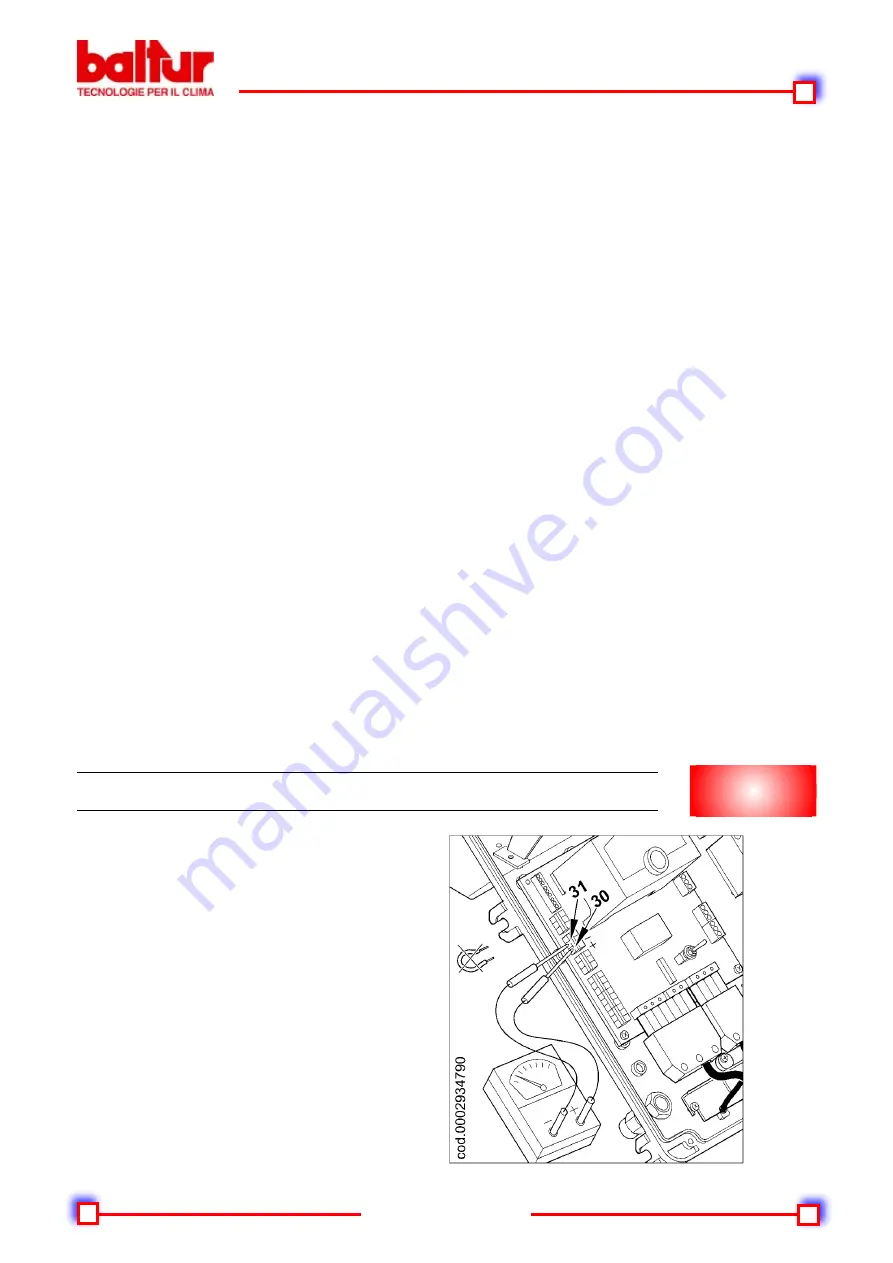
16) Check the triggering of the flame
detector (ionisation electro
de) by disconnecting the
jumper between terminals 30
and 31 on the printed circuit
board and switching
on the burner. The equipment
must run through its cycle com
pletely and, three seconds
after the ignition flame has for
med, “lock-out”.
This check must also be
carried out the burner already
on. Disconnecting the 30 and 31
jumper, the equipment must
immediately go into its “lock-out”
action.
17) Check the proper working of the
boiler thermostats or pressure
switches (when triggered they
must stop the burner).
N.B. Check that the switch on occurs
normally since if the adjuster is
shifted forward, it may happen that
the speed of the delivery air is so
high that ignition is difficult. If this
happens, the adjust must be shif-
ted back by degrees until it is in
a position in which ignition occurs
normally, and this new position can
be regarded as the final position.
We remind you that is preferable,
in the case of the small flame, to
limit the quantity of air to the least
possible needed for safe ignition,
even in the most difficult circum
-
stances.
To measure the ionisation current,
remove the jumper between terminals
30-31 on the printed circuit with the
burner off (see diagram). Connect a
microampmeter to the terminals (with
a suitable scale to have the burner
restart). Once the flame has appeared
it will be possible to measure the
ionisation current, the minimum value
of which to ensure the working of the
equipment is shown in the specific
wiring diagram. After making the
measurement, reset the jumper that
has been disconnected.
IONISATION CURRENT MEASUREMENT
N°0002934790


