5
P4
C2
P6
A2
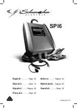
Attach Middle Panel (P4) to the Top Panel
(P5) as shown in illustration #3. Secure by
turning the Cam Locks (C1) 1/4 Turn until
they lock.
Attach Bottom Panel (P6) to the Middle Panel (P-4)
using 2 Wood Screws (A2).
Illustration # 3
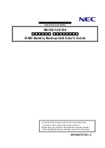
Illustration # 4
To Secure Cam Locks,
Insert Large Phillips
Head Screwdriver and
turn Cam Lock 1/4 turn
(90 degrees) clockwise.
Attach Right Leg Welded (P2) to the Top
and Bottom Panels (P5 & P6) using
6 CS Phil Screws (A1) as shown in
illustration #4. Just start the CS Phil
Screws (A1) at this point and do not
tighten.
P5
5.
7.
6.
C1
G
Press 2 Grommet Sleeves (M1) in
round openings in the Bottom
Panel (P6) as shown
in illustration #4.
Snap Grommet Cap (M2) over
top of Grommet
Sleeves (M1).
8.
9.
P6
P3
A1
P2
P5
M2
M1
A1
Place a Slotted End Panel (P3), large
space at top, in the recess inside the
Right Leg Welded (P2). .