


www.balluff.com
7
english
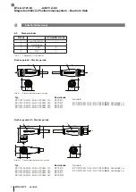
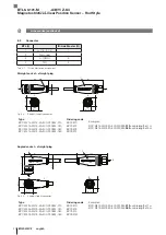
0.5 Ø 25
71
12.8
25
60
Ø 10.2
45
46
3.1
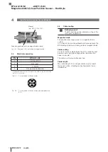
Construction
Electrical connection:
The electrical connection is made
via a connector (see Type code on page 23).
Housing:
Aluminum housing containing the processing
electronics.
Mounting thread:
We recommend assembling the BTL
on the mounting thread:
– BTL6-…-A/B: M18×1.5
– BTL6-…-Y/Z: 3/4"-16UNF
The BTL with Ø 10.2 mm has an additional thread at the
end of the rod to support larger nominal lengths.
Magnet:
Defines the position to be measured on the
waveguide. Magnets are available in various models and
must be ordered separately (see Accessories on
page 21).
Nominal length:
Defines the available measuring range.
Rods with a nominal length from 25 mm to 4572 mm are
available.
Damping zone:
Area at the end of the rod that cannot be
used for measurements, but which may be passed over.
3.2
Function
The BTL contains the waveguide which is protected by an
outer stainless steel tube (rod). A magnet is moved along
the waveguide. This magnet is connected to the system
part whose position is to be determined. The magnet
defines the position to be measured on the waveguide.
An internally generated INIT pulse interacts with the
magnetic field of the magnet to generate a torsional wave
in the waveguide which propagates at ultrasonic velocity.
The component of the torsional wave which arrives at the
end of the waveguide is absorbed in a damping zone to
prevent reflection. The component of the torsional wave
which arrives at the beginning of the waveguide is
converted by a coil into an electrical signal. The travel time
of the wave is used to calculate the position. The
measuring value is output as a 32-bit value with a sign
relative to the null point.
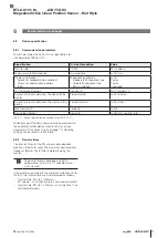
3.3
Number of magnets
Operation is possible with one or two magnets, where the
number can be fixed or flexible (see
page 18).
3
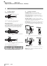
Construction and function
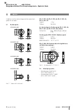
Fig. 3-1: BTL6-…, construction and function
1) Unusable area
2) Not included in scope of delivery
1)
BTL6-…-S4
Nominal length =
Measuring range
Mounting surface
B: 30-1 mm
Z: 2"-0.04"
Damping zone
Thread
M4×4/6 deep
1)
Magnet 2)
Thread size
B: M18×1.5
Z: 3/4"-16UNF
1)
Mounting surface
A: 30-1 mm
Y: 2"-0.04"
Thread size
A: M18x1.5
Y: 3/4"-16UNF
2)
Null point
End point
Output signal rising:
Error signal
100 %
0 %
BTL6-U101-M _ _ _ _ -A/B/Y/Z-S4
Magnetostrictive Linear Position Sensor – Rod Style
Summary of Contents for BTL6-U101-M****-A-S4 series
Page 2: ...www balluff com...
Page 3: ...BTL6 U101 M_ _ _ _ A B Y Z S4 Betriebsanleitung deutsch...
Page 4: ...www balluff com...
Page 27: ...BTL6 U101 M_ _ _ _ A B Y Z S4 User s Guide english...
Page 28: ...www balluff com...
Page 51: ...BTL6 U101 M_ _ _ _ A B Y Z S4 Notice d utilisation fran ais...
Page 52: ...www balluff com...
Page 75: ...BTL6 U101 M_ _ _ _ A B Y Z S4 Manuale d uso italiano...
Page 76: ...www balluff com...
Page 99: ...BTL6 U101 M_ _ _ _ A B Y Z S4 Manual de instrucciones espa ol...
Page 100: ...www balluff com...
Page 123: ......


