


1
BTL5-A/C/E1 _ -M _ _ _ _ -SF-SA364-F _ _
Micropulse Transducer - Rod Style
english
Installing the transducer
NOTICE!
Interference in function
Improper installation can compromise the function of the
transducer and result in increased wear.
►
Only vertical mounting is permitted!
►
The flange surface of the transducer must make full
contact with the mounting surface and be perfectly
sealed through the use of a seal and tri-clamp.
►
Mounting must be done in a manner where the rod
cannot touch the container wall. Deflection of the
rod to the side, e.g. through flow currents, must be
prevented by suitable brackets.
Installing the float
1.
Install the float (accessory) taking the orientation into
account (raised markings on top).
2.
Secure the float using the cotter pin, without placing
any mechanical loads on the rod. Guide the cotter pin
through the hole until it engages.
Installing the transducer
1.
Insert a suitable seal.
2.
Place the transducer on the mounting surface, so it
makes full contact and perfectly seals the hole.
3.
Fasten the transducer with a 1 1/2" tri-clamp.
Intended use
The BTL5 Micropulse Transducer, together with a machine
controller (e.g. PLC), comprises a position measuring
system. It is intended to be installed into a machine or
system. Flawless function in accordance with the
specifications in the technical data is ensured only when
using original BALLUFF accessories, use of any other
components will void the warranty.
Opening the transducer or non-approved use are not
permitted and will result in the loss of warranty and liability
claims against the manufacturer.
General safety notes
Installation
and
startup
may only be performed by
trained specialists.
The
operator
is responsible for ensuring that local safety
regulations are observed. In particular, the operator must
take steps to ensure that a defect in the position
measuring system will not result in hazards to persons or
equipment.
If defects and unresolvable faults occur in the transducer, it
should be taken out of service and secured against
unauthorized use.
User's guide download
A complete standard user's guide can be downloaded
from the Internet at
www.balluff.com/downloads-btl5
or requested via e-mail from
.
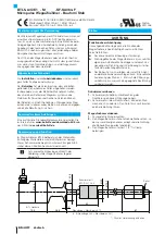
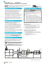
Dimensions and function
The BTL5 transducer contains the waveguide. A float is
moved along the waveguide. This float defines the position
to be measured on the waveguide.
Ensure vertical mounting! The transducer is
shown in a horizontal position in the Figure.
EU Directive 2004/108/EG (EMC Directive) and EMC law
Noise immunity: EN 61000-6-1/EN 61000-6-2
Emission: EN 61000-6-3/EN 61000-6-4
File no.
E227256
48.8
70.5
67
54
Ø 54.5
Ø 43.6
Ø 32
Ø 10.2
2
1) Not included in scope of delivery
Nominal length = Measuring range -15
(e.g. Nominal length 266 = Measuring range 281)
Cotter pin
Float 1)
BTL-S-3212-4Z
BTL housing


