background image

FLOOR MODEL ELECTRIC DECK OVEN OPERATION MANUAL

1

TABLE OF CONTENTS

INSTALLATION INSTRUCTIONS 

1

RECEIVING 1
LOCATION AND MINIMUM CLEARANCES 

1

INSTALLATION 1
STACKING 3
STEAM OPTION 

3

INSTALLATION OF DECKS 

4

ELECTRICAL CONNECTION 

5

SYSTEM CHECK 

6

INITIAL START-UP 

6

OPERATING INSTRUCTIONS 

7

GENERAL BAKING 

7

GENERAL BAKING TIPS 

7

SPECIAL FEATURES 

8

CLEANING 8
SERVICE AND TROUBLESHOOTING 

9

SERVICE AND TROUBLESHOOTING CHART 

10

RATING PLATE 

10

PARTS LIST W/EXPLODED VIEW 

11

WIRING DIAGRAMS 

13

WARRANTY 19

Models Covered

Model

Elements 

Per Deck

Total Kw  

Per deck

Phase

Model

Elements 

Per Deck

Total Kw  

Per deck

Phase

EP1(2,3)-8-3836 

8

8

1 or 3

EB1(2,3)-8-5736

12

12

1 or 3

EP1(2,3)-8-5736 

12

12

1 or 3

ER1(2,3)-12-3836

8

8

1 or 3

EB1(2,3)-8-3836 

8

8

1 or 3

ER1(2,3)-12-5736

12

12

1 or 3

INSTALLATION INSTRUCTIONS

Receiving

Read the notice on the outside carton regarding damage 
in transit. “CONCEALED DAMAGE”, damage discovered 
after opening the crate(s), must be reported immediately 
to the carrier. The carrier will perform an inspection of 
the damage and furnish forms for the consignee’s claim 
against the carrier. Retain all packing material- including 
outer carton until the inspection has been completed.

Location And Minimum Clearances

Adequate air space must be provided for proper venting 
of the controls and provisions must be made for venting 
of the cooking vapors. The Oven must be installed in a 
well-ventilated area and following minimum clearances 
must be maintained at all times: 

Ovens can be installed with “Zero” clearances (back 
and sides) from combustible and non-combustible 
materials.

The Ovens may be installed on combustible Flooring if 
mounted on the Legs provided. Keep the area around 
your oven free and clear of all combustible materials.

Installation

Place the oven and parts as close to the area of final 
installation before un-crating. Your oven is packed 
sitting on its back. Leave it on its back while unpacking. 
The pallet may be left under oven for convenience in 
further handling. Unpack carefully to avoid damage to 
the oven. If concealed damage is discovered, follow the 
instructions detailed in Receiving section above.

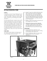
a)  Legs are shipped in a separate carton complete 

with mounting bolts and washers. Firmly bolt two 
legs (in case of casters, the two with the brakes 
must be used here) to the upper two corners 
(front) of the oven as it rests on the pallet. Note: 
(See Fig. 1).

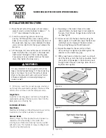
b)  Using sufficient help, tilt the oven forward and 

lower it down so that the two front legs come to 
rest on the floor. (See Fig.2)

Summary of Contents for EB series

Page 1: ...BUILT BY CRAFTSMEN TESTED BY TIME SERIES EP EB ER OPERATION MANUAL SUPERDECK SERIES ELECTRIC DECK OVENS ...

Page 2: ...d maintenance instructions thoroughly before installing or servicing this equipment CAUTION Instructions to be followed in the event the user smells gas must be posted in a prominent location in the kitchen area This information shall be obtained from the local gas supplier NOTICE BAKERS PRIDE OVEN COMPANY LLC 1307 N Watters Rd Suite 180 Allen TX 75013 Phone 800 527 2100 Fax 914 576 0605 www baker...

Page 3: ...rton until the inspection has been completed Location And Minimum Clearances Adequate air space must be provided for proper venting of the controls and provisions must be made for venting of the cooking vapors The Oven must be installed in a well ventilated area and following minimum clearances must be maintained at all times Ovens can be installed with Zero clearances back and sides from combusti...

Page 4: ...f casters release the brakes then reapply once in position maintaining the minimum distances specified in Minimum Clearances section above g Remove all loose parts and packages from the oven interior h Insert the short piece of tapered pipe supplied see fig 4 into the hole at the top located near the left rear corner of the oven see fig 5A Turn it to the desired direction mark the location of the ...

Page 5: ...stacking brackets Steam Option If this option has been ordered and supplied remove the control panel s and left access cover s to gain access to the steam plumbing as follows a Remove all screws and vent knob from the control panel Loosen the set screw on the thermostat knob and remove it Pull the control panel out at the bottom then down and out from the vent rod Slip the right flange hole of the...

Page 6: ...crew it into the lower pipe union Single Oven Insert the connecting pipe small end up through the appropriate opening of the base and screw it into the lower pipe union See fig 5e Installation Of Decks Steel Decks Steel Decks for Bake and Roast Application are factory installed and no further installation is required Ceramic Decks Ceramic Decks for Pizza Application are shipped in a separate carto...

Page 7: ...s in the complete installation and thence to an independent earth connection in compliance with EN 60335 1 and or local codes If flexible line cordage is used to connect the equipment it should be a minimum of H07RN F type conforming to EN60335 1 and or local codes Overexposure to smoke or fumes may cause nausea and dizziness Be sure the oven is placed in a well ventilated area CAUTION Field Conne...

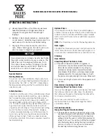
Page 8: ... three will stay that way until you turn the timer knob counter clockwise to 0 to switch them off or turn the knob clockwise for more time and repeat the above with the same or a different setting Ovens with Steam Option Never activate the steam timer when the oven is cold since the steam will immediately condense and turn to water a The steam timer can be adjusted from 1 to 60 seconds and has bee...

Page 9: ... F 290 C Pan baking refers to baking Pizza in pans Crusts can be thick or thin and toppings range from light to heavy Bake temperatures for pan baking range from 450 F 235 C to 500 F 260 C General Baking Tips a At day s end turn the thermostat to the 0 off position to conserve energy leaving the Top and Bottom Heat controls set for next day s operation b In the morning preheat for one hour at 50 F...

Page 10: ... no need to reduce both at the same time If less heat is required lower the thermostat setting Optional Timer Upon request an electric timer is provided to give an audible continuous signal at the end of a preset time up to 60 minutes 72 minutes with 50Hz supply on Bake Ovens and up to 5 hours 6 hours with 50Hz supply on Roast Ovens NOTE The Timer does not control the heating elements Oven Lights ...

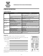
Page 11: ...ol switches indicator lamps contactors and heating elements b The infinite top and bottom heat control switches to see if they are on They must be in a set position other than off for indicator lamps contactors and heating elements to operate c The power supply fuses breakers to see if they are blown or have tripped d The two branch protection fuses in the control panel of the oven to see if one o...

Page 12: ...ter Bottom infinite switch set too low Increase setting Top infinite switch set too high Decrease setting Bottom of pies burn before toppings are cooked Deck temperature too hot especially during slow periods Reduce Thermostat setting by 50 75 below normal bake temperature When decks cool begin cooking and immediately increase the thermostat setting by 50 75 Bottom infinite switch set too high Dec...

Page 13: ...FLOOR MODEL ELECTRIC DECK OVEN OPERATION MANUAL 11 OPERATING INSTRUCTIONS Parts List and Exploded View Exploded View EP EB ER Electric 3836 5736 Deck Oven ...

Page 14: ...4 M1382A Electric Timer 250V 60 Minute 55 M1367A Infinite Switch 208V 25A Top Bottom Heat Control 56 M1368A Infinite Switch 240V 25A Top Bottom Heat Control 57 M1370A Hi Limit Switch 140C 240 120V 10 15A 58 M1371A Contactor 4 Pole 600V 25A 208V 50 60Hz 59 M1372A Contactor 4 Pole 600V 25A 220 240V 50 60 Hz 60 M1387A Solenoid Valve 1 2B 1 2P 61 M1374A Electric Timer 250V 5 Hour 62 M1388A Solenoid Co...

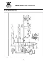
Page 15: ...FLOOR MODEL ELECTRIC DECK OVEN OPERATION MANUAL 13 OPERATING INSTRUCTIONS Wiring Diagrams Wiring Diagram EP B R 8 12 5736 208 240 or 440 480V 1PH 2W or 3PH 3W ...

Page 16: ...FLOOR MODEL ELECTRIC DECK OVEN OPERATION MANUAL 14 OPERATING INSTRUCTIONS Wiring Diagram EP B R 8 12 3836 208 240 or 440 480V 1PH 2W or 3PH 3W ...

Page 17: ...FLOOR MODEL ELECTRIC DECK OVEN OPERATION MANUAL 15 OPERATING INSTRUCTIONS Wiring Diagram EP B R 8 12 5736 230 400V STAR ...

Page 18: ...FLOOR MODEL ELECTRIC DECK OVEN OPERATION MANUAL 16 OPERATING INSTRUCTIONS Wiring Diagram EP B R 8 12 3836 230 400V STAR ...

Page 19: ...s and Valves are covered for a period of SIX MONTHS All Ceramic Baking Decks are covered for a period of THREE MONTHS The installation of these replacement decks is the responsibility of the purchaser The extended Cyclone door warranty years 3 through 5 is a parts only warranty and does not include labor travel mileage or any other charges EXCLUSIONS Negligence or acts of God Failures caused by er...

Page 20: ...TANT FOR FUTURE REFERENCE Please complete this information and retain this manual for the life of the equipment For Warranty Service and or Parts this information is required Model Number Serial Number Date Purchased ...

Page 21: ...19 NOTES ...

Page 22: ...t offering a wealth of refrigeration and cooking expertise Products include walk in coolers and freezers hot and cold display cabinets cases and storage systems commercial ovens rotisseries and cooking equipment and rotary vane pumps Ask your sales representative about how the power of all Standex brands can work for you www standex com segments food service Food Service Equipment Group ...

Reviews: