Chapter 1. Modbus Communications
4
Communications Options User’s Guide
Press
[EXIT]
until you return to
RUN
mode and the screen resumes the display of data measurements. Then reboot
the meter to load the new settings into memory.
1.4 MODBUS Register Map
To request specific parameters from the flowmeter using MODBUS, the control system must enter the appropriate
register number. Only registers 1 through 90 are available for MODBUS communications, while registers 508 through
512 are used by the flowmeter to store the MODBUS parameters. For details, see:
Table 2 on page 5 for a 1-Channel gas flowmeter (GC868, GF868, GM868, GN868, GS868, XGM868, XGS868)
Table 3 on page 6 for a 2-Channel gas flowmeter (GC868, GF868, GM868, GN868, GS868, XGM868, XGS868)
Table 4 on page 9 for a 1-Channel liquid flowmeter (DF868, XMT868i)
Table 5 on page 11 for a 2-Channel liquid flowmeter (DF868, XMT868i)
Table 6 on page 14 for a Sentinel flowmeter.
Refer to
Notes
on page 8, page 13, or page 16 for information about the numerical references.
Note:
Depending on the type of flowmeter being programmed, some MODBUS register numbers may have zero
readings. If this is the case, those register types are not available for that flowmeter.
Note:
If you request Ch2 or AVE data from a 1-Channel meter, the values will all be zero.
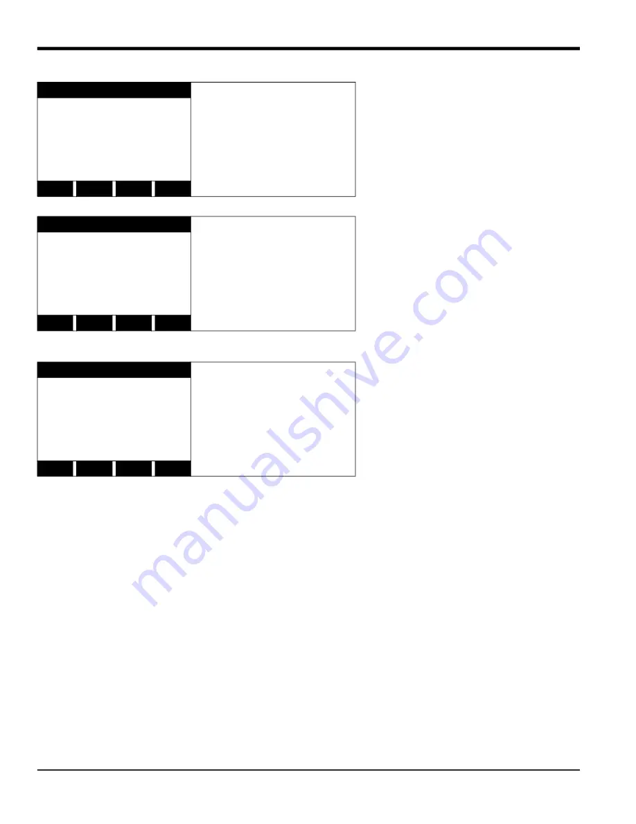
COMM PROGRAM
Press the appropriate
[Fx]
function key to select
[NONE]
,
[ODD]
, or
[EVEN]
for the
MODBUS parity setting.
MODBUS BAUD RATE
current value appears here
MODBUS PARITY
current setting appears here
none
odd
even
COMM PROGRAM
Press the appropriate
[Fx]
function key to select
[1]
or
[2]
for the MODBUS stop bits
setting.
MODBUS PARITY
current setting appears here
MODBUS STOP BITS
current setting appears here
1
2
COMM PROGRAM
Enter a MODBUS Address
number between 1 and 247.
Then, press
[ENT]
.
MODBUS STOP BITS
current setting appears here
MODBUS Address?
current address appears here


