background image

PanaFlow Z3 User’s Manual

45

Chapter 3. Programming

3.

Option I/O board

Note:

Consult the factory or BakerHughes Services before you upgrade software.

IMPORTANT:

The upgrade process may wipe out the configurations. It is important to save a site file before 
beginning the upgrade process. Use USB flash drive 8GB or 16GB for upgrade. 32GB flash drive is not 
supported.

3.0.1

Perform Software Upgrade

The XMT1000 software upgrade requires password entry. The Upgrade password is unique to the System serial 
number of your meter. The meter will automatically be exited from Upgrade mode after 5 minutes of inactivity. 
Ensure the meter keypad is in unlock mode. If the meter keypad is locked, use steps outlined in Section 3.2.1 to unlock 
the keypad. Log-in into Operator access level and navigate to About Meter and note the System Serial Number. Open 
the GENPASS_SW_UPGRADE application, enter the noted System Serial Number. The GENPASS_SW_UPGRADE 
application will show the Upgrade Access password for your meter.

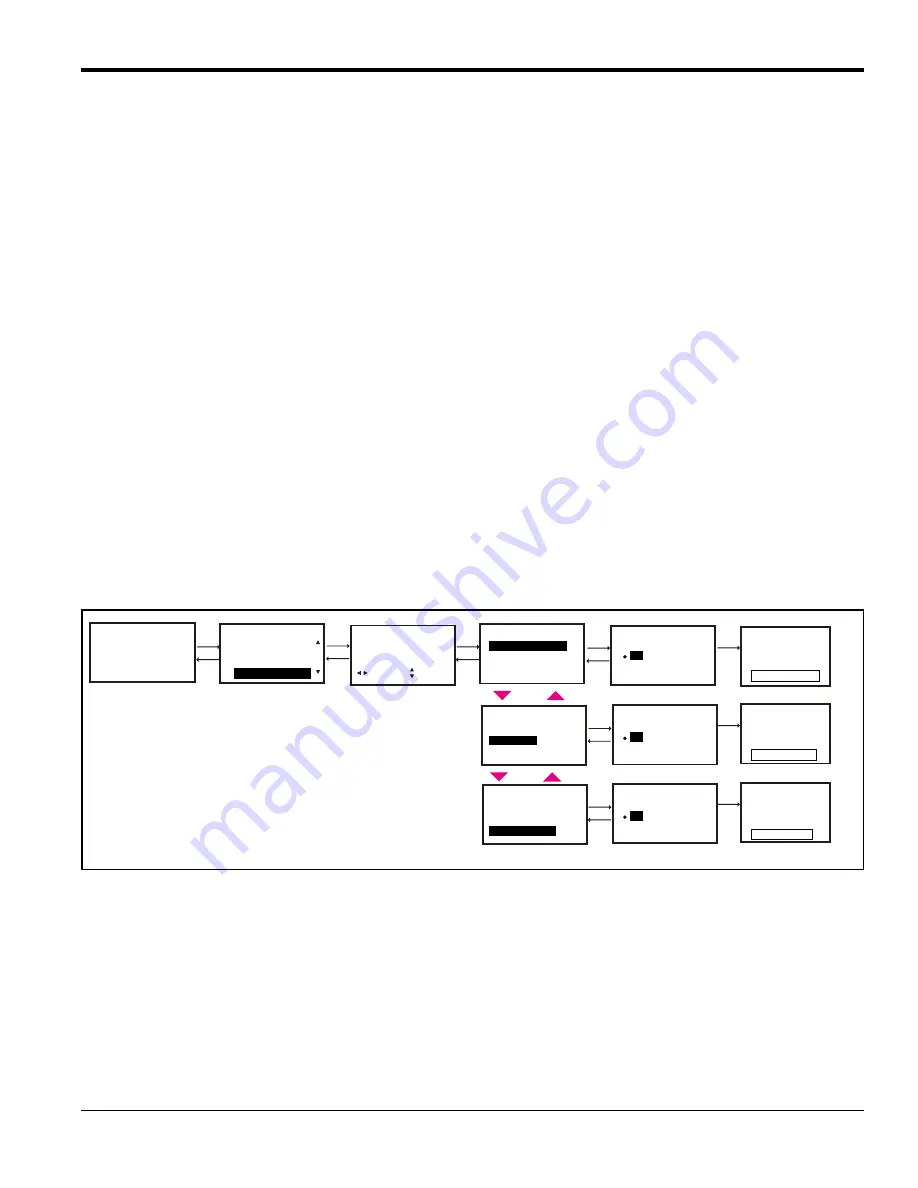
To perform Software Upgrade, do the following steps and refer Figure 39:

1.

Copy the Transmitter, Flow board or Option I/O board software into the USB flash drive and insert the USB flash 
drive to the meter.

2.

In the meter HMI press 

[

]

 until the lock icon on the meter's Measurement View display is highlighted, and press 

[ENTER]

.

3.

In the Main Menu select 

[Software Upgrade]

, then press 

[ENTER]

.

4.

Enter the password for your meter when prompted.

5.

Select the board you want to upgrade as outlined in the recommended sequence above.

6.

Confirm the initiation of upgrade by selecting 

[Yes]

. Once confirmed the upgrade process will start. The display 

indicates the steps in the process. The upgrade of each subsystem could take up to 10 minutes. At the end of the 
upgrade the meter displays if the upgrade was successful or not. The meter would restart after upgrade of each 
subsystem is complete. But it is recommended to power cycle the meter after successfully upgrading all sub 
systems. 

Figure 39: Software Upgrade

Velocity

0.000

   m/s

Main Menu

Errors/Warnings

Software Upgrade

Enter Upgrade password

Software Upgrade

Flow Info

Transmittter Board

Option IO Board

Flow Board

Software Upgrade

Transmittter Board

Option IO Board

Flow Board

Software Upgrade

Transmittter Board

Option IO Board

Flow Board

No

Yes

Keypad Lockout

111111
[        ]


2


9


[        ]

ESC

MOVE

[        ]

[        ]

ENTER

MODF


9


2


9


2


9


9


2


Upgrade Transmitter SW

No

Yes

UpgradeFlow Board SW


9


2


System Upgrade Window 
Upgrading Please wait..
Don’t touch any key!

Upgrading...

Upgrading...

Upgrading...


9


System Upgrade Window 
Upgrading Please wait..
Don’t touch any key!


9


System Upgrade Window 
Upgrading Please wait..

Don’t touch any key!


9


2


9


No

Yes

Upgrade Opt I/O Board SW


2


Summary of Contents for Panametrics PanaFlow Z3

Page 1: ...Flow 910 311 Rev C April 2019 Panametrics com PanaFlow Z3 User s Manual...

Page 2: ......

Page 3: ...Flow 910 311 Rev C Panametrics com PanaFlow Z3 Ultrasonic Flow Meter for Liquid Custody Transfer Measurement User s Manual 910 311 Rev C April 2019...

Page 4: ...ii no content intended for this page...

Page 5: ...rical Connections 11 2 4 1 Local Mount Configuration Transducer Wiring 12 2 4 2 Remote Mount Configuration Transducer Wiring 12 Chapter 3 Programming 3 1 Introduction 15 3 1 1 HMI Features 15 3 1 2 In...

Page 6: ...rror codes 47 4 3 1 1 Single Channel Error 47 4 3 1 2 Multi Channel Error 48 4 3 1 3 Viewing Channel Specific Error Warnings 48 4 3 1 4 Viewing Flow diagnostics 48 4 4 Fluid and Pipe Problems 52 4 4 1...

Page 7: ...Compatibility 78 Appendix B Data Records B 1 Electronics 87 B 1 1 Data Entry 87 B 2 Initial Settings 88 B 3 Diagnostic Parameters 91 Appendix C Modbus Map C 1 Input Registers Map 93 Appendix D CE Mar...

Page 8: ...Contents vi PanaFlow Z3 User s Manual...

Page 9: ...ese instructions carefully may cause unreliable performance Safety Issues Auxiliary Equipment Local Safety Standards The user must make sure that he operates all auxiliary equipment in accordance with...

Page 10: ...sure that operators and maintenance personnel have all safety equipment applicable to the auxiliary equipment Examples include safety glasses protective headgear safety shoes etc Unauthorized Operati...

Page 11: ...could impact health and the environment In order to avoid the dissemination of those substances in our environment and to diminish the pressure on the natural resources we encourage you to use the app...

Page 12: ...Preface x PanaFlow Z3 User s Manual no content intended for this page...

Page 13: ...ransducers and sensor body The XMT1000 is our latest ultrasonic flow transmitter with state of the art flow measurement capability in a rugged enclosure certified for use in hazardous areas The LX tra...

Page 14: ...etween transmission and reception of the ultrasonic signals is measured in both directions When the liquid in the pipe is not flowing the transit time downstream equals the transit time upstream When...

Page 15: ...s users to place the XMT1000 Transmitter at a separate location from the flowcell System configurations utilizing this remote mount option are supplied with a 2 pipe mounting bracket for XMT1000 elect...

Page 16: ...affixed to the PanaFlow Z3 which provide details and information about your system Three are located on the flowcell and two are located on the transmitter Figure 4 highlights the locations of all fiv...

Page 17: ...n the Specification Tag Plate Figure 6 The Specification Tag Plate contains information pertaining to the build and test of the pressure vessel In addition to the specifics of the following list Vesse...

Page 18: ...te The Part String and Serial Number Tag Plate contains the specific configuration of the pressure vessel as well as final assembly date BakerHughes serial number and customer tag information This can...

Page 19: ...acking the PanaFlow Z3 System Installing the Meter Body Site Considerations Making Electrical Connections WARNING The PanaFlow Z3 flow meter can measure the flow rate of many fluids some potentially h...

Page 20: ...Prior to installation inspect all material to be used in the installation including Nuts Bolts check for debris and damaged threads RF Flange Faces check for damage to serrations that may cause gasket...

Page 21: ...PanaFlow Z3 User s Manual 9 Chapter 2 Installation Figure 8 Lifting the PanaFlow Z3 System...

Page 22: ...least 10 pipe diameters of straight undisturbed flow upstream and at least 5 pipe diameters of straight undisturbed flow downstream from the measurement point see Figure 9 Undisturbed flow means avoi...

Page 23: ...all joints and seams protecting the insulation against puncture tears or other damage 2 3 3 Fluid Comments Gas To avoid measurement errors suitable measures should be taken to make sure that the line...

Page 24: ...Remote Mount Configuration Transducer Wiring Wiring the transmitter electronics to the remote flowcell setup is done by attaching the transmitter s cable gland to the six SMB jacks shown in Figure 11...

Page 25: ...PanaFlow Z3 User s Manual 13 Chapter 2 Installation Figure 12 Remote Mount Wiring Diagram...

Page 26: ...Chapter 2 Installation 14 PanaFlow Z3 User s Manual no content intended for this page...

Page 27: ...estricted to only those users with the proper passcodes 3 1 1 HMI Features Figure 13 PanaFlow Z3 HMI The six keys on the magnetic keypad are used to program the PanaFlow Z3 Key Symbol Key Name Functio...

Page 28: ...changeable passwords after commissioning the meter 3 2 1 Unlock from Keypad Lockout After power up if the meter s Measurement View Refer Figure 14 shows a lock icon on the top right of the display use...

Page 29: ...ement to display on the Measurement View do the following steps and refer Figure 16 1 Press until the Measurement name on the meter s Measurement View display is highlighted and press ENTER 2 In the D...

Page 30: ...View and press ENTER 0 000 m s Display Measurement Channel 1 Channel 2 Channel 3 Composite Inv Vol Measure Composite Velocity Volumetric Act Volumetric Std Composite Raw Velocity 9 2 9 Velocity m s m...

Page 31: ...iew and press ENTER 0 000 m s Display Measurement Channel 2 Channel 3 Composite Ch1 Inv Vol Measure Channel 1 Velocity Volumetric Act Volumetric Std Channel 1 Raw Velocity 9 2 9 Velocity m s m s 0 000...

Page 32: ...9 2 9 or Totalizer Composite Rev Vol Batch Net Vol Batch Batch Time Fwd Vol Batch Totalizer Channel 1 Rev Vol Batch Net Vol Batch Batch Time Fwd Vol Batch Totalizer Channel 1 Totalizer Channel 2 Chan...

Page 33: ...Steps and Primary pages IMPORTANT If the keypad has not been pressed for 5 minutes the XMT1000 exits the Program and returns to displaying measurements Because changes can only be retained after the u...

Page 34: ...SL min SL hr SL d Sm s Sm min Sm hr Sm d SCFH SCFM SBBLD SBBLH SBBLM SBBLS SCFD SCFS Mass Units kg s kg min kg h kg d Ton s Ton min Ton h Ton d lb s lb min lb h lb d klb s klb min klb h klb d STon s...

Page 35: ...ange password Operator Ch 1 Dn Display Backlight Display Backlight Always On Backlight Timeout 10 s About Meter Meter Tag Password Operator No Yes Enter new Operator password 111111 2 9 UNDO MOVE SAVE...

Page 36: ...page Then select Communication Port and press ENTER Figure 22 below shows the options available Figure 22 Modbus Port Setting Input Output Analog Output Std Communication Port Address Parity Baud Rat...

Page 37: ...the Path Error Handling set to ON see Figure 36 changes the Output response See Table 4 for Analog Output response with Path Error Handling set to ON Note Table 4 assumes Composite Actual Volumetric...

Page 38: ...Volumetric Act No Yes Yes E23 MultiChAccuracy Measured Composite Volumetric Act mA proportional to the Measured Composite Volumetric Act Yes No Yes E23 MultiChAccuracy Measured Composite Volumetric Ac...

Page 39: ...s 20 00mA 0 01mA If the value on the multimeter is not 20 00mA 0 01mA input the value read on the multimeter into the Calibrate 20mA value and press ENTER Check multimeter again verify the Current rea...

Page 40: ...ach option For measurement options available on Pulse Output refer to Table 6 Table 5 Pulse Output Options Option Functional Description Polarity Choose the Negative or Positive edge of the pulse Meas...

Page 41: ...se Value 10 00 m 3 Pulse Pulse Value Polarity Pulse Width Measurement Type Pulse Pulse Value Polarity Pulse Width Measurement Type Pulse Width 5 00 ms Test Pulse Pulse Pulse Value Error Handling Pulse...

Page 42: ...for Frequency Output Composite Velocity Actual Volumetric Standard Volumetric Mass Flow Average Volumetric Flow Rate Sound speed Reynolds Channel x Velocity Actual Volumetric Standard Volumetric Mass...

Page 43: ...Composite Measurement Type Comp Pulse Frequency Base Value Full Value Full Frequency Measurement Type Velocity Volumetric Act Soundspeed Volumetric Std Avg Vol Flow Rate Mass Flow Mass Flow Base Value...

Page 44: ...site Volumetric Act Frequency proportional to the Measured Composite Volumetric Act No No Yes E22 SingleChAccuracy Measured Composite Volumetric Act Frequency proportional to the Measured Composite Vo...

Page 45: ...nt Options for Frequency Output Composite Velocity Actual Volumetric Standard Volumetric Mass Flow Average Volumetric Flow Rate Sound speed Reynolds Channel x Velocity Actual Volumetric Standard Volum...

Page 46: ...arm Value UNIT m s 10 00 Alarm Value Alarm Value 10 000 m s Alarm Alarm Value Alarm Type Measurement Type Measurement Type Composite Measurement Type CH 1 Reynolds SNR Up Gain Std Deviation Gain Measu...

Page 47: ...ass Full Value Full Value Analog Output Calibrate Base Value Error Handling 10 ft 3 s Full Value Input Output Analog Output Std Option Comm Slot 1 About HART Analog Output Base Value Full Value Calibr...

Page 48: ...Output S2 1 or Analog Output S2 2 and press ENTER 3 If you do not wish to connect an Analog Output you should turn Analog Output selection to OFF 4 If you are connecting an Analog Output choose 4 20m...

Page 49: ...er reads 4 00mA 0 01mA If the value on the multimeter is not 4 00mA 0 01mA input the value read on the multimeter into the Calibrate 4mA value and press ENTER Check the multimeter again verify that th...

Page 50: ...and verified the Analog output is successfully calibrated 11 Once calibration is complete select either Save or Save Logout option to save calibration data Figure 30 Optional I O Analog Output Channe...

Page 51: ...NTER to accept the current 4 mA value or Press ESCAPE to cancel the calibration 8 Select Calibrate 20mA in the meter Menu Set 20mA current on calibrated current source and check the reading on the XMT...

Page 52: ...d press ENTER 4 Select RTD Input and press ENTER 5 Set the number of Calibration points by selecting No of RTD Cal points 6 Scroll down and select Calibrate option 7 Select Set point 1 press ENTER and...

Page 53: ...f the fluid flowing through the pipe that is required to ensure accurate ultrasonic flow rate measurements Use steps as in section Section 3 3 2 to navigate to the Programming page 1 Select Composite...

Page 54: ...ic Viscosity Fixed KV Off Other 9 2 9 2 9 2 9 2 9 2 9 or 9 2 9 9 2 Density Act 62 4 Lb Ft 3 Density Act 9 2 Fluid Type Standard Water 0 to 260 C Fluid Type Soundspeed Limits Min Soundspeed Standard Ot...

Page 55: ...ty for early warning indications on the LCD and Errors 4 To cutoff the near zero measurements program an appropriate value in Zero Cutoff a In order to see stable averaged flow program the time window...

Page 56: ...ntil Save options are displayed on the menu Highlight Save or Save Logout and Press ENTER to save settings The meter will not use the changed setting to make measurements until the settings are explic...

Page 57: ...l the lock icon on the meter s Measurement View display is highlighted and press ENTER 3 In the Main Menu select Software Upgrade then press ENTER 4 Enter the password for your meter when prompted 5 S...

Page 58: ...Chapter 3 Programming 46 PanaFlow Z3 User s Manual no content intended for this page...

Page 59: ...nsducers a built in error code message system greatly simplifies the troubleshooting process All the possible PanaFlow Z3 error code messages are discussed in this chapter along with the possible caus...

Page 60: ...lso check 1 Incorrect programming on Error Limits or flow condition changes that now make previous programming invalid 2 Defective Damaged cables transducers couplant buffer or electronics In case you...

Page 61: ...ions If Active Tw measurement is not valid then check the value entered in SNR Min Error Limits option Refer Programming Chapter Also refer to Fluid and Pipe Problems and Transducer Problems sections...

Page 62: ...er than 35 dB change the Transmit Voltage to High Refer Programming Chapter Refer to Fluid and Pipe Problems and Transducer Problems sections to correct any issues Gather required diagnostics data bef...

Page 63: ...tion is not self recovering and will not automatically correct itself Try power cycling the meter If error persists after power cycle contact BakerHughes factory E29 Velocity Warning The measured velo...

Page 64: ...ement point This causes problems resulting from gas bubbles in the fluid Cavitation can usually be controlled through proper system design The fluid must not excessively attenuate ultrasound signals S...

Page 65: ...ansducer from the flowcell and carefully inspect the buffer electrical connector and the transducer face for roughness and or pitting Any transducer damaged in this manner must be replaced Contact Bak...

Page 66: ...ls Figure 42 Service Test Points The test points are GATE Gate connection is input to start and stop flow calibration process This input detects an outside source contact closure A closure can be prog...

Page 67: ...e warning Warning The value programmed for the parameter was out of range and hence discarded Please enter a valid range S5 Unsupported Parameter This parameter is not supported Warning A read or writ...

Page 68: ...n failed Please verify all the configuration parameters If error persists contact BakerHughes factory S24 DSP Hardware Errors DSP hardware failed Fault DSP hardware failure detected Try power cycling...

Page 69: ...Recommended Actions Error Code Error Message Description Recommended Action C1 Flow COMM Error Flow board communication error Transmitter cannot communicate to the flow measurement unit Try power cyc...

Page 70: ...ower cycling the meter If error persists after power cycle contact BakerHughes factory X13 Get GUI Node Fail Failed to generate GUI Failed to generate GUI Try power cycling the meter If error persists...

Page 71: ...wer cycling the meter If error persists after power cycle contact BakerHughes factory A11 S2 4 Input NotConnect Analog Input Error occurs when 4 20mA input is not connected at Channel S2 4 RTD Input E...

Page 72: ...rom top channel to bottom channel then that can be an indication of a problem with the path SNR Up Signal to noise ratio of the upstream transducer 30 5 SNR value between 5 and 30 shall provide valid...

Page 73: ...20 dB Active Tw Gain Down Active Tw gain setting on downstream transducer 20 dB 20 dB Transit Time Up Upstream ultrasonic signal transit time N A N A Transit Time Down Downstream ultrasonic signal tr...

Page 74: ...Chapter 4 Error Codes and Troubleshooting 62 PanaFlow Z3 User s Manual no content intended for this page...

Page 75: ...re 43 Flanges Sensor Ports Transmitter Connection Figure 43 Serviceable Interfaces WARNING Before opening the vessel it must not contain any pressure This warning pertains to all three interfaces desc...

Page 76: ...larger flowcell sizes all transducer paths may be located on the same plane 2 Relieve potential pressure build up by loosening the Pressure Relief Plug on the bottom of the Upstream A Plane Sensor Qua...

Page 77: ...PanaFlow Z3 User s Manual 65 Chapter 5 Maintenance and Service Figure 44 Upstream A Plane and B Plane Sensor Quadrants View 1 Top Figure 45 Upstream A Plane Sensor Quadrant View 2 Front...

Page 78: ...the adapter and remove them using an appropriate hex drive tool Once these are completely removed they can be stored in a safe location 4 The entire XMT1000 Transmitter should now be free to rotate ab...

Page 79: ...fied service technicians should remove the XMT1000 Transmitter from the flow meter adapter The XMT1000 Transmitter contains transducer wiring and sensitive electronics Modification or alteration in an...

Page 80: ...ics Panametrics Flow meter representative with the serial number of the meter located as shown on the Part String and Serial Number Tag Plate If it is determined that a flow transducer has been damage...

Page 81: ...es below 1 6 ft s 0 5 m s Accuracy statement assumes measurement of a single phase homogenous liquid with a fully developed symmetrical flow profile passing through the meter typically 10 diameters up...

Page 82: ...to 302 F 40 C to 150 C Remote mount 40 F to 302 F 40 C to 150 C Maximum process temperature is 203 F 95 C when additional analog input output options are selected Pressure Range Up to maximum allowabl...

Page 83: ...Mounting Local or remote mounting Paths Three paths 3 to 24 in 80 to 600 mm Two paths 2 in 50 mm Display English 128 x 64 mono color LCD display configurable for single or dual measurement parameters...

Page 84: ...m One or two isolated four wire RTD temperature inputs 148 F to 662 F 100 C to 350 C 100 Ohm or 1000 Ohm platinum Digital Interfaces Standard RS485 Modbus Optional HART 7 0 protocol with 4 dynamic var...

Page 85: ...PanaFlow Z3 User s Manual 73 Appendix A Specifications and Model Configurations A 4 Serial Number Information...

Page 86: ...Appendix A Specifications and Model Configurations 74 PanaFlow Z3 User s Manual...

Page 87: ...PanaFlow Z3 User s Manual 75 Appendix A Specifications and Model Configurations Note Other meter body materials can be offered on request Please consult factory...

Page 88: ...mation as per ASME 16 5 standards 0 200 400 600 800 1000 1200 1400 1600 40 45 5 131 216 5 302 PRESSURE PSIG TEMPERATURE F SA 352 GR LCC 0 200 400 600 800 1000 1200 1400 1600 40 45 5 131 216 5 302 PRES...

Page 89: ...92 1 DIN standards SA 352 GR LCC GROUP 3E1 0 10 20 30 40 50 60 70 40 7 5 55 102 5 150 PRESSURE BARG TEMPERATURE C SA 351 GR CF8M GROUP 14E0 0 10 20 30 40 50 60 70 40 7 5 55 102 5 150 PRESSURE BARG TEM...

Page 90: ...in process fluids may detriment the performance of these O rings therefore impacting the effectiveness and safety of the system overall Typical applications of O rings composed of EPDM or Viton For mo...

Page 91: ...20 508 21 0 533 44 1117 45 1142 72 16 EN 1092 1 PN 63 WN TYPE 11 8 5 214 20 508 21 3 540 44 1117 45 3 1150 75 17 4 IN ASME 150 RF WN 11 7 297 17 4 441 9 228 20 508 21 9 556 11 7 297 44 1117 45 9 1165...

Page 92: ...615 62 1574 60 6 1540 48 2 1225 501 66 ASME 300 RF WN 25 5 647 40 1016 37 6 955 64 1625 61 6 1565 605 67 ASME 600 RF WN 27 685 42 1066 38 4 974 66 1676 62 4 1584 731 68 EN 1092 1 PN 10 WN TYPE 11 22 2...

Page 93: ...MINIMUM RECOMMENDED MAINTENANCE CLEARANCE ON EITHER SIDE A Z X CZ ALLOW 12 0 305 MINIMUM RECOMMENDED MAINTENANCE CLEARANCE ON EITHER SIDE CX ALLOW 12 0 305 MINIMUM RECOMMENDED MAINTENANCE CLEARANCE ON...

Page 94: ...8 3 209 20 508 13 329 44 1117 37 939 71 12 EN 1092 1 PN 10 WN TYPE 11 7 9 199 20 508 12 8 324 44 1117 36 8 934 63 13 EN 1092 1 PN 16 WN TYPE 11 7 9 199 20 508 12 8 324 44 1117 36 8 934 63 14 EN 1092...

Page 95: ...28 4 722 24 2 615 62 1574 52 4 1331 48 2 1225 494 66 ASME 300 RF WN 25 5 647 40 1016 29 4 747 64 1625 53 4 1357 598 67 ASME 600 RF WN 27 685 42 1066 30 2 766 66 1676 54 2 1376 724 68 EN 1092 1 PN 10...

Page 96: ...tline installation Z3 2 24 inch flow meter system remote mount D Y CY ALLOW 12 0 305 MINIMUM RECOMMENDED MAINTENANCE CLEARANCE ON EITHER SIDE Z A X CX ALLOW 12 0 305 MINIMUM RECOMMENDED MAINTENANCE CL...

Page 97: ...EM SHOWN RIGID CONDUIT AND CONDUIT SEALS WHICH ARE TO BE SUPPLIED BY CUSTOMER NOT SHOWN FOR SIMPLICITY SEE NOTE 6 7 FLOWCELL TRANSMITTER HEAD CUSTOMER TO SUPPLY 2 INCH PIPE A DETAIL A 6X RIGHT ANGLE S...

Page 98: ...BEL AFTER INSTALLATION TRANSMITTER HEAD ASSEMBLY 14 KG DETAIL B INTRINSICALLY SAFE BARRIER PROVIDED WITH FOUNDATION FIELDBUS ONLY 6X RIGHT ANGLE MCX PLUG CONNECTORS CONNECT PER LABELING ON CABLE AND B...

Page 99: ...ds Appendix B Data Records B 1 Electronics B 1 1 Data Entry Record complete and detailed service data for the PanaFlow Z3 in Table 25 below Make additional copies of the table as needed Table 25 Servi...

Page 100: ...Appendix B Data Records 88 PanaFlow Z3 User s Manual B 2 Initial Settings Table 25 Service Record cont Date Description of Service Performed By...

Page 101: ...Volumetric Net Batch Totals Inventory Forward Inventory Reverse Inventory Net Inventory Time Channel 1 Velocity Channel 1 Sound Speed Channel 1 Transit Time Up Channel 1 Transit Time Down Channel 1 De...

Page 102: ...namic Threshold Up Channel 2 Dynamic Threshold Down Channel 3 Velocity Channel 3 Sound Speed Channel 3 Transit Time Up Channel 3 Transit Time Down Channel 3 Delta T Channel 3 Up Signal Quality Channel...

Page 103: ...l values can then be compared to current values to help diagnose any future malfunction of the system Table 27 Diagnostic Parameters Parameter Channel 1 Channel 2 Channel 3 Initial Current Initial Cur...

Page 104: ...Appendix B Data Records 92 PanaFlow Z3 User s Manual no content intended for this page...

Page 105: ...PanaFlow Z3 User s Manual 93 Appendix C Modbus Map Appendix C Modbus Map C 1 Input Registers Map...

Page 106: ...odbus Map 94 PanaFlow Z3 User s Manual Note Most Modbus Masters add an offset of 1 to the actual register addresses For Example Meter Modbus address 0x8200 Address to input in the Modbus master applic...

Page 107: ...e and all connections must be properly shielded and grounded Refer to Table 28 below for the specific requirements Note If the PanaFlow Z3 is wired as described in this appendix the unit will comply w...

Page 108: ...Appendix D CE Mark Compliance 96 PanaFlow Z3 User s Manual no content intended for this page...

Page 109: ...icular purpose and warranties arising from course of dealing or usage or trade Return Policy If a Panametrics Panametrics Flow meter instrument malfunctions within the warranty period the following pr...

Page 110: ...Warranty 98 PanaFlow Z3 User s Manual no content intended for this page...

Page 111: ...lameproof enclosure are not permitted The apparatus should be de energized before opening Installation shall be in accordance with the installation instructions and the National Electrical Code ANSI N...

Page 112: ...ser must ensure that any cable and cable entry devices used with the equipment are suitable for use at temperatures above 90 C The end user is to ensure appropriate earthing upon installation The temp...

Page 113: ...133M6993 Rev B 101 of 104 Certification Safety Statements for PanaFlow PF10 Zx Apr 2019 REMOTE MOUNT CERTIFICATION TAG FLOWCELL SPECIFICATION TAG...

Page 114: ...Certification Safety Statements for PanaFlow PF10 Zx Apr 2019 133M6993 Rev B 102 of 104 SERIAL NUMBER AND MODEL CODE TAG Connection and Wiring Diagram REMOTE MOUNT WIRING...

Page 115: ...133M6993 Rev B 103 of 104 Certification Safety Statements for PanaFlow PF10 Zx Apr 2019 LOCAL MOUNT WIRING...

Page 116: ......

Page 117: ......

Page 118: ...and company names are trademarks of their respective holders 910 311 Rev C Customer Support Centers U S A The Boston Center 1100 Technology Park Drive Billerica MA 01821 U S A Tel 800 833 9438 toll f...

Reviews: