6 | Baker Hughes
Copyright 2020 Baker Hughes Company. All rights reserved.
Introduction
The following instructions are designed to assist maintenance
personnel in performing most of the maintenance required on
the 37002 Series valve. Baker Hughes has highly skilled service
people around the world available for startup, maintenance and
repair of our valves and component parts. In addition, a regularly
scheduled training program is conducted to train customer service
and instrumentation personnel in the operation, maintenance and
application of our control valves and instruments. Arrangements
for these services can be made through your local Baker Hughes
Representative. When performing maintenance use only Baker
Hughes replacement parts. Parts are obtainable through your
local Masoneilan Representative. When ordering parts always
include Model and Serial Number of the unit being repaired.
These installation and maintenance instructions apply to all
sizes and ratings of the Masoneilan 37002 Series control valves,
regardless of the type of trim used. The model number, size and
rating of the valve are shown on the identification tags located
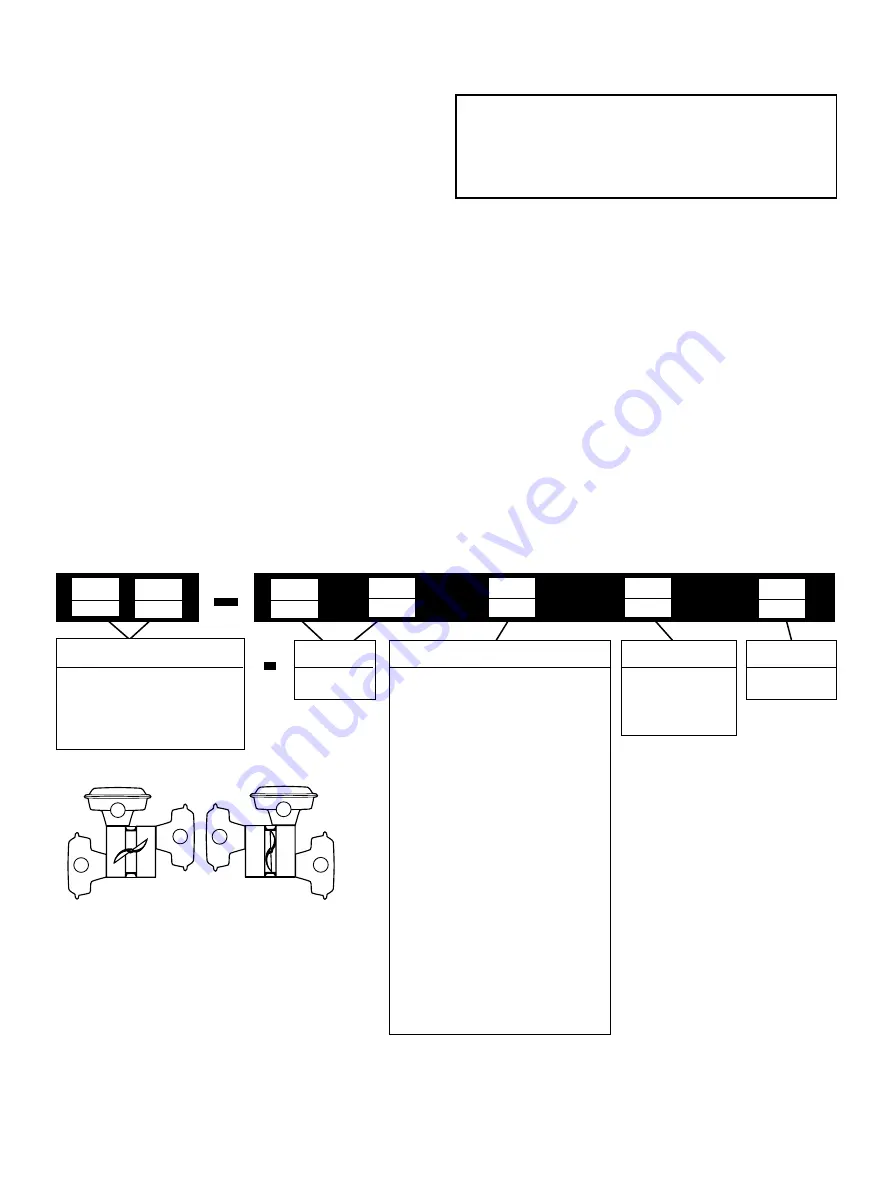
on the actuator. Refer to Figure 1 to identify valve nomenclature.
Unpacking
Care must be exercised when unpacking the valve to prevent
damage to the accessories and component parts. Should any
problems arise contact your Baker Hughes Representative or
Sales Office.
Installation
1. The valve is flangeless and has a rating of 300 lb ANSI. It
may be installed between machined flanges of the following
ANSI standards; 125 lb., 150 lb., 250 lb.. and 300 lb. ANSI
flanges as well as DIN (ND) 10, 16, 25 and 40 metric flanges.
2. Before installing the valve in the line, clean piping and
valve of all foreign materials, such as welding chips, scale,
oil, grease or dirt. Gasket surfaces should be thoroughly
cleaned to ensure leak proof joints.
3. To allow for inline inspection, maintenance and removal of
the valve without service interruption, provide a manually
operated stop valve on each side of the valve with a manually
operated throttling valve mounted in the bypass line.
4. The valve may be installed in the line so that the control
substance will flow in either direction. However, the actuator
must be located in one of the recommended positions
shown in Figure 1.
CAUTION
CAUTION
WARNING
DANGER
Prior to installing the valve in the line, this section
should be completely reviewed and understood.
Numbering System
4th
3rd
33. Spring Diaphragm
(Air-To-Extend action
only, with or without
auxiliary handwheel)
2nd
7
2nd
1st
3
1st
3
5th
2
Actuator Type
1. Unlined
2. Elastomer
Lined
Bore Type
0. Undefined
1. Horizontal above centre.
Valve closes on stem extension
(air-to-close action)
2. Horizontal above centre.
Valve opens on stem extension
(air-to-open action)
*3.Vertical above centre.
Valve closes on stem extension
(air-to-close action)
*4. Vertical above centre.
Valve opens on stem extension
(air-to-open action)
5. Horizontal below centre.
Valve closes on stem extension
(air-to-close action)
6. Horizontal below centre.
Valve opens on stem extension
(air-to-open action)
*Standard actuator mounting arrangement
Actuator Mounting
2
Design Series
Body Series
37
5
1
3
6
4
2
Air-to-Close
Air-to-Open
Actuator in front of line
Unnumbered actuator positions above same as
numbered positions when valve is rotated 180° in line.
Figure 1


