12 | Baker Hughes
Copyright 2020 Baker Hughes Company. All rights reserved.
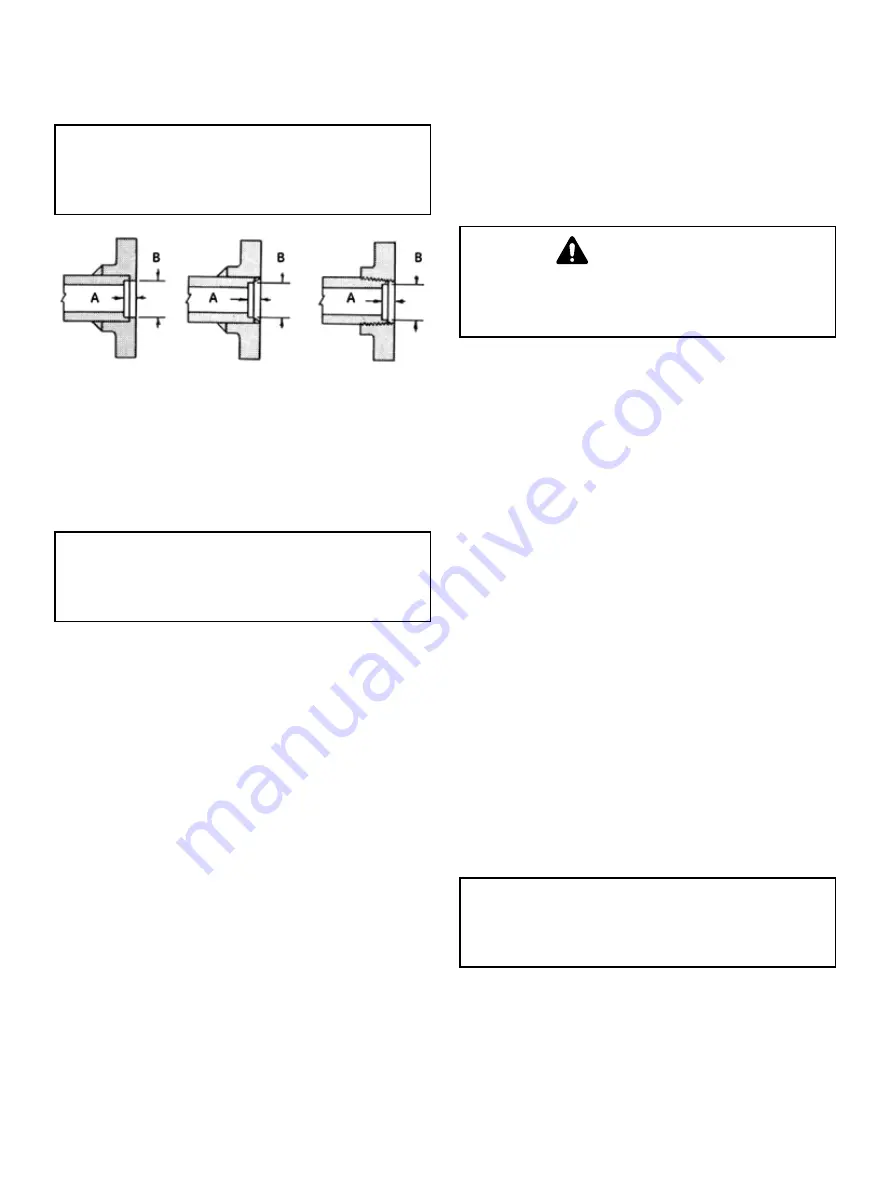
Weld Neck Flanges
150 lb and 300 lb ANSI weld neck flanges have standard bore
which matches 37000 Series MiniTork Butterfly valve bore.
CAUTION
CAUTION
WARNING
DANGER
Slip on and screwed flanges not recommended for
lined valves.
Figure 10
Actuator Air Piping
The MiniTork II actuator is designed to accept 1/4“ NPT air supply
piping. Use 1/4“ 0.D. tubing, or equivalent for all air lines. If the air
line exceeds 25’ in length or if the valve is equipped with volume
boosters, 3/8“ tubing is preferred. All connections must be free
of leaks.
CAUTION
CAUTION
WARNING
DANGER
Do not exceed loading pressure indicated on the
warning tag located on the diaphragm cover.
Changing Actuator Position
For each valve action, air to open or air to close, the actuator
and bracket may be mounted in any one of three recommended
positions (See Figure 1). Actuator position is usually determined
by adjacent piping, obstacles of various types or air piping
arrangements. If for example, the valve orientation is Position
6, but the valve must be installed in Position 2, simply rotate the
entire unit 180° around the axis of the shaft and install in the line. In
such a case, no disassembly is required other than repositioning
gauges so that they are not upside down. However, if the valve
orientation must be changed from Position 2 to Position 4, partial
disassembly is required. Depending on whether the valve is or is
not equipped with the handwheel and whether the valve is lined
or unlined, select the appropriate section in this instruction and
proceed.
Changing Actuator Action
For the positions shown in Figure 1, the valve action is air to
open or air to close. In both cases the actuator stem extends with
admission of air to the actuator. Changing valve action requires
partial disassembly in repositioning the actuator to the other hole
in the bracket. If the valve is equipped with a handwheel, it must
be repositioned to the opposite side of the bracket.
Note: The handwheel is always installed so it operates
against the actuator spring force. The handwheel is always
located on the same side of the bracket as the actuator
(See Figures 12 and 13). Depending on whether the valve
is or is not equipped with the handwheel and whether the
valve is lined or unlined, select the appropriate section on
disassembly and proceed.
Maintenance
CAUTION
CAUTION
WARNING
DANGER
Prior to performing maintenance on the valve, isolate
the valve, vent the process pressure and shut off all
electrical signal air and supply lines to the unit.
This section is primarily addressed to recommended routine
maintenance required on the valve which does not require
complete disassembly. Routine maintenance is limited to the
packing box and diaphragm replacement.
Packing Box
Packing box maintenance is one of the principal chores of
routine servicing. Tightness of the packing is obtained through
compression which is achieved by evenly tightening packing
stud nuts (23A) against a packing flange (22). Care must be
taken not to over tighten as this could prevent smooth operation
of the valve. If all compression is used up and the valve leaks
around the stem, new packing is required.
Note: If replacement of all packing is required, the valve
must be disassembled. Refer to appropriate section.
The following procedure should be used for temporary repairs
only.
A. Loosen and remove packing flange stud nuts (23A).
B. Slide packing flange (22) and packing follower (8)
down the shaft.
Note: As a temporary repair, it may be desirable
to simply add more packing, since removal of any
packing while the valve is assembled to the actuator is
difficult. In addition, only one or two pieces of packing
can be removed without disassembly. String packing,
compatible with the service, can be used as a temporary
repair, however it must be replaced with the correct
packing as soon as possible.
C. Add or replace packing as desired.
CAUTION
CAUTION
WARNING
DANGER
Do not over-tighten. Nuts should be tightened only
enough to stop leakage.
D. Slide packing follower (8) and packing flange (22)
back into position.
E. Replace and evenly tighten packing flange stud nuts
(23A).
F. Place valve back in service and check for leaking.


