background image

7

CLEANING
The vehicle must be cleaned periodically by using
pressurised water.  Before cleaning the vehicle cover the
important parts like ignition switch, silencer, ignition unit,
H.T. coil,starter motor by plastic bags.  Don’t apply the jet
of water directly towards electrical parts such as switches,
ignition unit, coils etc. otherwise they may get damaged.

Brushing with parafin and wiping dry with clean rag is
advisable for external cleaning of the engine.  All painted
surfaces should be washed with water.  Do not use
kerosene or detergent soap on painted surfaces as it
damages the paint and turns it dull.

If necessary, blow with compressed dry air, the head lamp
reflector, clean or wipe off dust with a very soft feather
brush.  After washing, dry the vehicle and carry out the
lubrication.

WARNING: Washing your scooter will allow the brakes to
become wet, with the same effect as riding on a wet road.
Whenever the brakes become wet, always dry them by
gently applying the brakes, repeatedly, until the heat
causes the brakes to dry and full brake function is
restored. Failure to follow this procedure can lead to loss
of brake effectiveness and a serious accident.

PERIODIC MAINTENANCE
Periodic maintenance (in accordance with the periodic
maintenance chart) of a vehicle is most important to
prolong its life , trouble free running and ensure your safety
while driving.

LUBRICATION
To reduce the friction between two moving parts lubricate
them periodically.  Insufficient lubrication will cause rapid
wear, damaging the parts prematurely.  Lubricate everytime
after washing the vehicle and whenever the vehicle is
operated under wet, rainy conditions.  Before lubricating,
clean off any rusty parts and wipe off old grease, oil or dirt.

A few drops of oil are effective to keep bolts and nuts away
from rusting and sticking.  This makes removal easier.
Please refer lubrication chart, for details of lubrication.

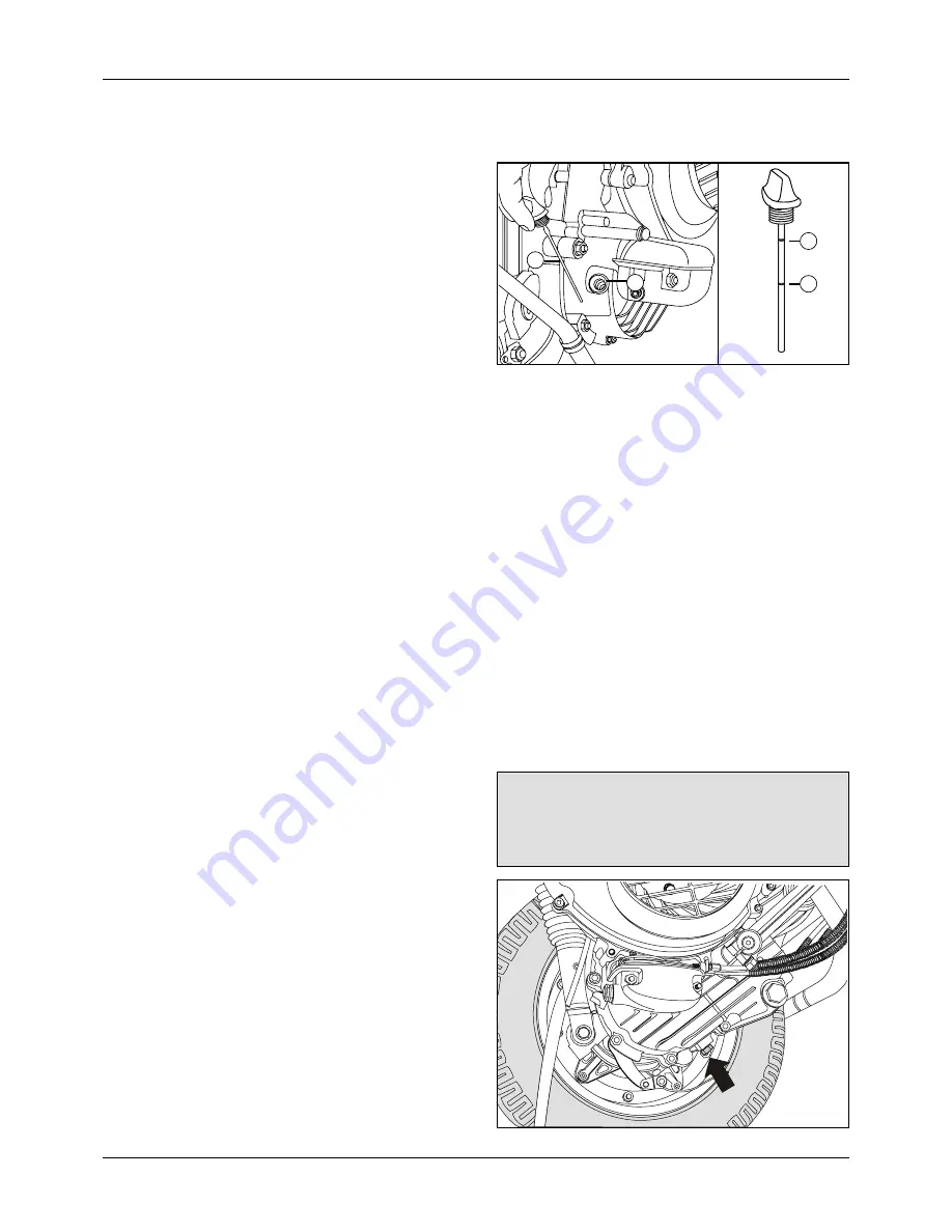
ENGINE OIL : Check engine oil  level daily.
For proper functioning of  cylinder block / piston , crankshaft,
tappets, clutch and transmission, the oil should be
maintained at an appropriate level.

Oil level inspection :

l

Place the vehicle on centre stand, on a level ground.

l

Clean the surface area around the oil filler opening.

l

Unscrew the dipstick from oil filler opening hole and
wipe it dry.

l

Put the dip stick, on oil filler opening , take out the dip
stick and observe the oil level on it.

l

There are two marks engraved on it.  If the level is
below the lower level mark, top up  with  the
appropriate quantity of recommended oil up to upper
level mark. If the oil level is too high i.e. above
the upper level mark, drain some oil from drain hole.

l

Fit back the dipstick and tighten it securely.

l

Ensure that there is no oil leakage.

A) Oil filler hole

B)  Oil level gauge

C) Upper level

D)  Lower level

Oil replacement:
If the  oil is used for a longer duration its lubricating
performance deteriorates.  So it is necessary to replace
the oil in accordance with periodic maintenance chart.
For replacing the oil follow the procedure given below :

l

Run the vehicle for few minutes.

l

Place the vehicle on main stand.  Let the oil settle.

l

Remove the oil drain bolt with its aluminium washer.
Also take out dip stick. Let the oil drain completely.
Tighten the drain bolt with new aluminium washer
securely. (Tightening torque 2.6 - 3.0  kg.m.)

l

By using a funnel pour the recommended oil from  the
oil filler opening hole or open Inlet tappet cover & pour
oil.

l

Fit back the dip stick and tighten it securely.

l

Ensure that there is no oil leakage.

Do not use inferior grade of oil as a replacement for
the recommended oil, otherwise it will lead towards
engine troubles.

  Oil capacity: 1100 ml  (For newly assembled engine)

                    : 1000 ml  (For drain & refill)

  Recommended oil : SAE 20 W40 of API SC/SF grade

  Replace oil after every  5000 kms / 3000 miles.

Drain bolt

SCHEDULED MAINTENANCE

C

A

B

D

Summary of Contents for Legend 00300728

Page 1: ...Service Station Manual Service Station Manual USA MODEL NO 00300728...

Page 2: ...een taken to make it as complete and accurate as possible All procedures and specifications subject to change without prior notice The right is reserved to make changes at any time without prior notic...

Page 3: ...s points of particular interest for more efficient convenient and safe operation It is essential that you do not neglect these instructions while carrying out repairs so as to avoid any personnel inju...

Page 4: ...rvicing 6 7 Scheduled Maintenance 7 13 8 General Precautions Dismantling assembly 14 15 9 Tightening Torques 16 17 10 Special Tools 18 21 11 Engine Exploded View 22 12 Dismantling and Assembly Engine...

Page 5: ...cle that can help identification Serial numbers with prefix 28 C and 28 E are stamped on chassis and engine of the vehicle in the position indicated in the figures below Chassis number Engine number T...

Page 6: ...ction type Brake size Front 150 mm dia 5 91 Rear 130 mm dia 5 12 Tires Front 3 50 X 10 4 P R Rear 3 50 X 10 4 P R Tire pressure FRONT 1 25 kg cm2 18 Psi REAR without pillion 1 75 kg cm2 25 Psi REAR wi...

Page 7: ...indicator switch is OFF and supplementary engine stop switch in RUN position lPress the Start Button to start the engine lRelease start button as soon as engine starts When engine is cold lPull the ch...

Page 8: ...optimum driving speed of 18 to 25 mph l Don t waste petrol by stop and go riding and by sudden starts and stops l Avoid harsh braking Do not brake unless it is very essential anticipateyourstops turns...

Page 9: ...l Replace 6000 MILES l l 6 Carburettor cleaning overhaul l l l l l 7 Fuel line Fuel Filter element cleaning l l l l Fuel Filter replacement if required 6000 MILES l l 8 Check adjust valve clearance l...

Page 10: ...n as per lubrication chart l l l l l 11 Check steering cum ignition lock other lock l forproperoperation 12 Check for smooth operation of choke lever l andaccelerator 13 Check front rear brakes for ef...

Page 11: ...se refer lubrication chart for details of lubrication ENGINE OIL Check engine oil level daily Forproperfunctioningof cylinderblock piston crankshaft tappets clutch and transmission the oil should be m...

Page 12: ...as specified in periodic maintenance chart If the engine is operating correctly and the machine is being ridden properly the colour at the electrode tip will be greyish yellow to light brown The centr...

Page 13: ...ly at low engine rpm and cause improper ignition timing Also throttle valve will not open completely in full throttle condition Ontheotherhand iftheacceleratorgriphasno play control of carburettor thr...

Page 14: ...Remove 5 nuts 3 special 2 regular and take out front wheel assly l After mounting wheel check the sequence of 5 mounting nuts Rear wheel nuts Inspection window Installation l Install the rear wheel o...

Page 15: ...er lubrication for free movement of inner cablesintheoutercasing Forcheckinganyofthecontrol cables follow the procedure given below l Disconnect the inner cable l Check free movement of the cable with...

Page 16: ...kers bulb remove 2 screws for lens take out lens replace bulb Removal of screws for lens Front blinker bulb replacement l Remove 2 mounting screws for nose grill and take out nose grill l Remove 2 mou...

Page 17: ...e neatly Make sure that the storage area is well ventilated and free from any source of flames or spark l Remove battery from vehicle l Maintain electrolyte level at Upper Level l Ensure that battery...

Page 18: ...aks them GENERAL PRECAUTIONS Dismantling assembly Before Servicing Before starting to service a vehicle careful reading of the applicable section is recommended to eliminate unnecessary work Photograp...

Page 19: ...should be applied to any rubbing surface which has lost its lubricative film Old grease and dirtyoilshouldbecleanedoff Deterioratedgrease has lost its lubricative quality and may contain abrasive fore...

Page 20: ...to Crankcase Qty 2 1 3 to 1 5 12 Kick lever 2 0 to 2 5 BOLTS FOR 13 Cylinder head to Cylinder Block Qty 2 0 9 to 1 1 14 Silencer to Crankcase Qty 1 3 0 to 3 5 15 Cam shaft sprocket 1 1 to 1 3 16 Cam...

Page 21: ...on chassis 3 0 to 4 0 4 Engine mounting on link 3 5 to 4 0 5 Pivot securing wheel hub 5 0 to 5 5 6 Wheel assly on brake drum Qty 5 2 0 to 2 7 BOLTS FOR 7 Handle bar mounting 3 2 to 3 8 8 Rear shock ab...

Page 22: ...ter bearing driver for installing front brake drum bearing 6 37 1014 14 Inner driver To be used with holder outer bearing driver for installing input shaft bearing in crankcase clutch side needle bear...

Page 23: ...t exhaust valves by compressing valve spring in cylinder head 13 37 1031 52 Clutch holder Used for hold the clutch housing stationary while loosening tightening the clutch hub nut 7 37 1028 32 Spur ge...

Page 24: ...ter For removing speedometer gear spacer from front wheel brake drum To be used with 37 1001 14 18 37 1801 06 Bearing races assembly tool To be used for installing the upper and lower bearing race on...

Page 25: ...1 Compression Tester To be used for checking compression pressure in the cylinder 25 37 1030 63 Hand tester For checking electrical components Refer Electrical Maintenance 26 69 7505 26 69 7505 28 Tor...

Page 26: ...22...

Page 27: ...ect fuel pipe and sensing pipe l Remove silencer by removing 2 nuts at the exhaust port of cylinder block and 1 bolt on crankcase arm l Remove bolt fixing lower end of rear shock absorber to the engin...

Page 28: ...ug cap and spark plug l Remove cam chain tensioner by removing 2 bolts fitted on cylinder block l Removeintakemanifoldbyremoving3boltsfittedon cylinder head l Remove OHC cover by removing 2 flanged bo...

Page 29: ...l of cylinder head l Remove one of the piston pin snap rings l Push out the piston pin and remove the piston Removal of piston assly MAGNETO ASSEMBLY DISMANTLING l Remove 4 bolts mounting fan on rotor...

Page 30: ...ngwith holder plate Removal of plunger A B Bolts for holder l Hold the wheel clutch with the help of clutch holder 37 1031 52 Remove clutch hub nut NOTE HUB NUT HAS LEFT HAND THREADING Clutch holder l...

Page 31: ...and store them properly Crankcase joining nuts l Gently tap the crankcase magneto side with the help of nylon mallet and take out l Remove crankshaft assembly alongwith float control rubber ring l Ta...

Page 32: ...th internal lever and plain washer l Remove O ring Main Shaft Mainshaft assly dismantling l Push the cup slightly towards the gear wheels l Press both the springs for gear selector against the gear se...

Page 33: ...her on other side of gear Remove circlip and take out ratchet gear l Remove spring coil and cup kick shaft l Remove circlip Kick Shaft Dismantling ENGINE ASSEMBLY REASSEMBLING OF SUB ASSEMBLIES Kick S...

Page 34: ...otate cross by 90 Check that the projection provided at the centre of cross is facing upwards l Assemblegearselectorinsidemainshaft Matchthe projection on the cross with the slot of gear selector Chec...

Page 35: ...screw l Fit oil drain plug alongwith washer l Assemble adjuster for clutch cable Crankcase Magneto Side l Assemble needle roller bearing with the help of special tool P No 37 1005 04 l Press magneto s...

Page 36: ...ft assembly in the needle roller bearing by meshing it with intermediate shaft gears Assembly of mainshaft l Assemble 2 no of dowels on crankcase l Assemble the centre gasket on to the crankcase l Ass...

Page 37: ...n criss cross pattern l Assemble collar bearing on holding plate l Assemble 2 dowels on crankcase clutch side l Fix gasket for clutch cover l Assemble clutch cover on crankcase clutch side l Prefix 6...

Page 38: ...astle nut on mainshaft Tighten the castle nut Fit the cap on castle nut and lock it with split pin Fitment of rear brake drum on mainshaft l Assemble 2 dowels on crankcase One on clutch side and the o...

Page 39: ...ng on cylinder head Also check that both the valvesareinclosedpositionbycheckingfreenessof tappets Set tappet clearance on intake valve with the help of feeler gauge and tappet tightening tool Lock th...

Page 40: ...PRESSURE 12 1 kg cm2 4 VALVES Tappet clearance In Exh engine cold 0 08 0 12 mm 0 003 to 0 005 Valve Inlet head thickness 0 7 0 15 mm Valve Exhaust head thickness 1 0 0 15 mm Valve Inlet stem diameter...

Page 41: ...ond ring 1 0 mm Piston ring end gap a Top ring 0 2 0 45 mm b Second ring 0 2 0 45 mm Piston ring gap position Top ring Towards Exhaust side Second ring Towards Inlet side Top oil rail 300 left of Exha...

Page 42: ...n T Nose l Remove 2 screws mounting LH blinker and slide out blinker assly from nose l Similarly dismantle RH blinker l Remove4boltsforBeeper Flashermountingbracket and horn l Take out horn l Remove 2...

Page 43: ...BAR COVER FRONT l Remove 2 spring clip nuts from cover l Remove 2 screws for mounting Head lamp mounting brackets l Screw In the Head lamp beam adjustment screw and take it out from the inner side of...

Page 44: ...ly with hinge b Dismantling of dual seat l Remove 2 nuts mounting the hinge bracket on seat alongwithspringwashers l Remove split pin plain washer and remove pin holding hinge bracket with seat hinge...

Page 45: ...andlelocatedinnerside chassis below tail lamp l Remove 2 nuts attaching grab handle with carrier plate Take out grab handle assly B Dismantling of grab handle l Remove 2 screws for tail lamp lens l Re...

Page 46: ...ignition switch b Screw for lock cam l Press the lug of lock and pull the lock barrel assly with key Ensure that spring plate will not fall down REMOVAL DISMANTLINGOFSTEERINGCOLUMN l Remove handle bar...

Page 47: ...w lock nut and upper bearing race Take care to hold steering column to avoid it from falling down Remove upper and lower steering ball cage Removal of Lock plate a l Tilt the scooter on one side and t...

Page 48: ...itting Speedometer gear and Spacer on Front brake drum use Special Tool Outer driver P No 37 1519 04 Metallic portion of Speedometer should face downward while assembling This tool consists of three p...

Page 49: ...m bearing driver set punch Grease seal into Front brake panel Assembly of Grease seal l Assemble Grease nipple on Front brake panel l Insert Front brake Actuating shaft assly into Front brake panel l...

Page 50: ...ith engine mounting link on chassis l Take out the engine carefully from the chassis CHASSIS ASSEMBLY l Assemblevariousgrommetsonchassisinrespective holes i e grommets for petrol pipes tail lamp contr...

Page 51: ...ervice limit 2 5 mm Rear 4 03 mm Service limit 2 5 mm 4 BRAKEACTUATINGSHAFTDIAMETER Front 12 925 12 968mm Rear 11 957 11 984mm 5 BRAKE ACTUATING SHAFT HOLE DIAMETER Front 13 043 mm Rear 12 027 mm 6 BR...

Page 52: ...tofallonahardsurface Such a shock to the parts can damage them l To prevent damage to electrical parts do not dis connect the battery leads or any other electrical connections when the ignition switch...

Page 53: ...eading Red Switch pressed x10 ohms Blue Switchreleased 0 ohms C STEERING CUM IGNITION SWITCH Connect the ve meter lead to Red cable and ve meter lead to Black cable Check continuity 0 ohms as given be...

Page 54: ...battery ve terminal l All DC load viz Brake lights and Side indicator bulbs are to be switched OFF l Start the Engine Set the Engine RPM at 3500 RPM l Measure Battery charging current It should be 1 0...

Page 55: ...th the help of screw driver rotate the screw till the horn sound is good l After proper tune up hold the screw lock the checknut 2 DC Current Measurement l RemovetheOrangewirefromHorn connectonelead o...

Page 56: ...ATIVE VE LEAD CONNECTION RANGE X 10 W 1 2 3 4 6 7 8 9 1 40 60 W 0 2 250 400 W 40 60 W 250 400 W 3 40 60 W 250 400 W 40 60 W 4 6 7 8 9 0 40 60 W M C D I UNIT With TRICS METER POSITIVE VE LEAD CONNECTIO...

Page 57: ...crank the engine instead of a kick when button is pressed The starter motor draws it current from a 12V 9 AH battery through a relay solenoid switch The solenoid switch relay is energized by pressing...

Page 58: ...e checked by using Hydrometer having small diameter spout Such a Hydrometer is available in Spare Part Dept or can be directly procured from market For measuring the specific gravity bring the electro...

Page 59: ...thin the battery are affected and results in loss of capacity Mostly the causes of sulphation are as under a Undercharging b Standing in a partially or completely discharged condition for long time c...

Page 60: ...f click noise comes b Refer 1 3 if click noise does not come 1 1 1 No response indicates that 12 V D C supply is not available at the starter motor S M terminal S The starter circuit needs to be check...

Page 61: ...5 Check for 12V DC supply between Red White wire in the coupler for Ignition Switch and chassis ground If the meter does not show supply then cable from fuse to the Ignition switch coupler may be open...

Page 62: ...is burnt replace armature Replace bush bearing Replace armature Lubricate pinion and shaft helix with light oil Deburr by filing and clean up Remove the starter from the vehicle and replace drive ass...

Page 63: ...60...

Page 64: ...Pilot jet clogged l Incorrect position of needle jet l Carburettorholderloose l Inlet manifold bolt loose l Insulator O rings cut or insulator loose l Air filter clogged or dry i e oil not applied l...

Page 65: ...y l Play between front brake drum and axle excessive l Hub pin or roller bearings worn out l Front shock absorber weak or hard l Excessiveclearancebetweenenginefoundationarm and engine link assly INEF...

Page 66: ...optimum performance Get fully familiarised with dismantling assembly procedures as given in this manual Always use genuine Bajaj Spares for replacement Use special tools developed for disassembling a...

Reviews: