background image


30 

30 

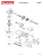
PARTS DIAGRAM 


Summary of Contents for BG-679

Page 1: ...LLC IS PROHIBITED Baileigh Industrial Holdings LLC Inc does not assume and hereby disclaims any liability for any damage or loss caused by an omission or error in this Operator s Manual resulting fro...

Page 2: ...LIFTING 14 INSTALLATION 15 Anchoring the Machine 15 OVERALL DIMENSIONS 16 GETTING TO KNOW YOUR MACHINE 17 ASSEMBLY AND SET UP 19 ELECTRICAL 23 MACHINE ADJUSTMENTS 26 Belt Tracking 26 Height and Angle...

Page 3: ...n notice to Seller of any suspected defect in the Goods prior to the expiration of the warranty period The original end user must also obtain a RGA from Seller prior to returning any Goods to Seller f...

Page 4: ...emedies provided under this Agreement or at law or equity Attorney s Fees In the event legal action is necessary to recover monies due from Buyer or to enforce any provision of this Agreement Buyer sh...

Page 5: ...Description of the functional parts of the machine Capacity charts Setup and start up instructions Machine operation Scheduled maintenance Parts lists GENERAL NOTES After receiving your equipment remo...

Page 6: ...zardous situation which if not avoided will result in death or serious injury WARNING Indicates a hazardous situation which if not avoided could result in death or serious injury CAUTION Indicates a h...

Page 7: ...tive devices such as ear muffs or earplugs to protect against objectionable or uncomfortable loud noises DUST HAZARD Wear appropriate dust mask Dust created while using machinery can cause cancer birt...

Page 8: ...he machine causing serious personal injury DO NOT operate without guards in place HIGH VOLTAGE USE CAUTION IN HIGH VOLTAGE AREAS DO NOT assume the power to be off FOLLOW PROPER LOCKOUT PROCEDURES EMER...

Page 9: ...igh does not recommend or endorse making any modifications or alterations to a Baileigh machine Modifications or alterations to a machine may pose a substantial risk of injury to the operator or other...

Page 10: ...affect proper machine operation 14 Observe work area conditions DO NOT use machines or power tools in damp or wet locations Do not expose to rain Keep work area well lighted DO NOT use electrically p...

Page 11: ...ble 32 Use spark and debris arresting apparatus Such apparatus should be connected to the machine so as to contain dust and debris that is generated and to suppress sparks thereby limiting human inhal...

Page 12: ...a etc as appropriate to your machine Understand and follow the operating requirements provided by the manufacturer of these materials WARNING Certain alloys such as titanium may create conditions wher...

Page 13: ...ment can be reached at 920 684 4990 and asking for the support desk for purchased machines Tech Support handles questions on machine setup schematics warranty issues and individual parts needs other t...

Page 14: ...age painted surfaces Follow manufacturer s label instructions when using any type of cleaning product After cleaning wipe unpainted metal surfaces with a light coating of quality oil or grease for pro...

Page 15: ...3 Item Name Qty Item Name Qty 1 Grinder 1 4 Hardware Hex Bolt pivot Flat Washer Nylon Insert Locknut 1 2 1 2 Welded Stand 1 5 Dust Bag with Clamp 1 3 Exhaust Blower with Motor 1 6 Spark Trap 1 1 5 3 4...

Page 16: ...to the floor Level the machine so that all the supporting feet are taking the weight of the machine and no rocking is taking place Follow these guidelines when lifting crane or hoist Always lift and c...

Page 17: ...the precise placement of it to the mounting surface FLOOR This machine distributes a large amount of weight over a small area Make certain that the floor is capable of supporting the weight of the ma...

Page 18: ...16 16 OVERALL DIMENSIONS 51 00 1295 4 44 00 1118 24 00 610 Belt Travel...

Page 19: ...17 17 GETTING TO KNOW YOUR MACHINE A P B E O N C G I H D F J K L M...

Page 20: ...port 1 E Belt Guard 1 F Tracking Adjuster 1 G Belt Tension Release Lever 1 H Stop Emergency Stop Button 1 I Spring Loaded Angle Adjustment Pin 1 J Steering Roller 1 K Dust Collection 1 L Side Cover 1...

Page 21: ...cure on the opposite side with a flat washer and a hex nut Do not overtighten as the grinder will need to pivot on the stand The grinder is shown in place with the pivot bolt secured and the adjustmen...

Page 22: ...20 20 Attaching the Bag 1 Slip the bag over the duct housing as shown and secure with the clamp 2 Tighten securely...

Page 23: ...he spring loaded steering roller closer to the contact wheel allowing you to place the belt around the wheels Note The direction arrows on the belt must match the belt travel direction 5 Remove the ol...

Page 24: ...Trap 1 Slide the spark trap onto the front of the grinder and secure with the flat washer and hex bolt Note Make sure the spark trap does not interfere with the opening of the hinged side access door...

Page 25: ...n low voltage will damage the motor In the event of a malfunction or breakdown grounding provides a path of least resistance for electric current to reduce the risk of electric shock This machine is e...

Page 26: ...machine toward the power supply a Route the power cord so that it will NOT become entangled in the machine in any way b Route the cord to the power supply in a way that does NOT create a trip hazard 3...

Page 27: ...nals L1 to W L2 to V L3 to U 8 Connect the ground wire typically green to the E terminal 9 Adjust the Thermal Overload setting up to the 17A position 10 Install the cover onto the electrical box Be su...

Page 28: ...the tracking of the belt 3 After clearing the area of any tools piece parts etc start the drive motor 4 Adjust the tracking of the belt with the tracking adjuster hex bolt F as explained above Retigh...

Page 29: ...essed against the belt and turned and ground as needed Surface Grinding 1 Before grinding make sure the exhaust fan with the collection bag attached is running and that the spark trap is in place 2 Op...

Page 30: ...od working order Weekly Maintenance On a weekly basis clean the machine and the area around it Lubricate threaded components and sliding devices Apply rust inhibitive lubricant to all non painted surf...

Page 31: ...me prepare the machine as follows Detach the plugs from the electrical supply panel Clean and lubricate the machine Remove the belt Cover the machine Note Baileigh Industrial offers an assortment of b...

Page 32: ...30 30 PARTS DIAGRAM...

Page 33: ...Washer 8mm 2 16 Socket Capscrew M8 x 20mm 2 17 Limiting Position Plate 1 18 Lock Washer 10mm 2 19 Socket Capscrew M10 x 25mm 2 20 Socket Capscrew M5 x 50mm 1 21 Eye Protector Base 1 22 Machine Screw...

Page 34: ...46 Hex Bolt M10 x 35mm 1 47 Flat Washer 6mm 4 48 Hex Bolt M6 x 16mm 4 49 Side Cover 1 50 Belt 2000mm x 150mm 1 51 Hex Bolt M8 x 20mm 6 52 Spring Washer 8mm 6 53 Support 1 54 Draw Bar 1 55 Pin Shaft 1...

Page 35: ...Qty 69 Slip Support 1 70 Hex Bolt M10 x 20mm 2 71 Spring Washer 10mm 2 72 Lock Washer 10mm 2 73 Hex Nut M10 4 74 Lock Washer M10 4 75 Hex Bolt M10 x 55mm 4 76 Motor 4 hp 220V 1 ph 1 77 Switch Box 1 7...

Page 36: ...34 34 ELECTRICAL SCHEMATIC M1 M2 TA1 SB1 KM1 FR KM1 FR KM1 3PH L1 L2 L3 PE U1 V1 W1 MAIN MOTOR DUST COLLECTOR MOTOR 2 3 4 U2 V2 W2 4Hp 2 94Kw 75Hp 56Kw...

Page 37: ...CKING 1 Improper belt splice 2 Worn wheel bearings 1 Check belt for irregular seam or shape 2 Check all bearings for overheating or damage Replace worn or damaged bearings CONTACT WHEEL WEAR 1 Grindin...

Page 38: ...36 36 NOTES...

Page 39: ...37 37 NOTES...

Page 40: ...TOWOC WI 54220 PHONE 920 684 4990 FAX 920 684 3944 www baileigh com BAILEIGH INDUSTRIAL HOLDINGS LTD UNIT D SWIFT POINT SWIFT VALLEY INDUSTRIAL ESTATE RUGBY WEST MIDLANDS CV21 1QH UNITED KINGDOM PHONE...

Reviews: