20
20
Belt Tracking
Note:
As the construction of each abrasive belt varies you may need to adjust the
Belt Tracking for each belt used on the BG-248-3. Also as belts wear Belt Tracking may be
required.
Grinding sharp internal square corners can be done on the Tool Rest by tracking the belt over
the edge of the contact wheel by 1/32” (0.031”) [0.8mm] to 1/16” (0.0625”) [1.6mm]. Be sure to
re track the belt when this operation finished avoiding damage to contact wheels as detailed
earlier in this document.
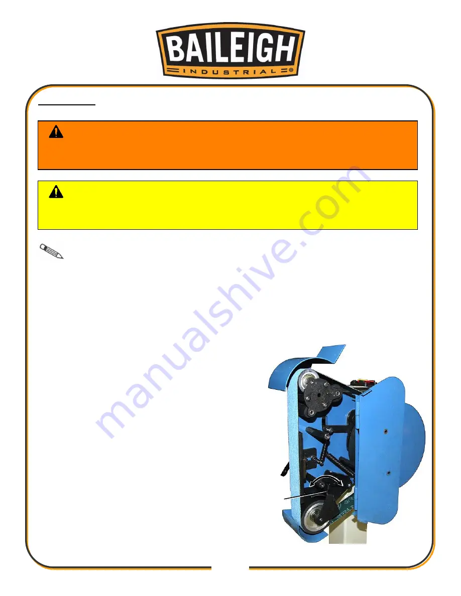
1. Belt tracking is the side to side adjustment of the
belt over the contact wheels. This can be achieved
by toggling the tracking lever (A).
2. As the tracking lever is displayed in the figure at
right;
a. Pulling the tracking lever toward the left will
cause the belt to track inward.
b. Pushing the tracking lever toward the right
will cause the belt to track outward.
3. Plug the machine into the power supply and start
the motor.
4. With the machine running, adjust the tracking by
moving the tracking lever left or right (as shown in
this figure) to cause the belt position to cover the
contact wheels.
5. When the tracking is set, stop the motor and close
and secure the upper cover.
WARNING:
Belt tracking is completed with the motor running and the
upper belt guard open. The operator MUST focus on the adjustment process to
prevent entanglement injury with the belt and rollers.
CAUTION:
Always ensure that the belt completely covers the contact
wheels. Failure to do this can result in damage to the contact wheel and possible
serious injury to operator and or by standers.
A


