background image


36 

36 

c.  Loosen the jam nut and turn adjusting stop screw (B) on the front trunnion in, or out 

until the blade is at 90º. 

d.  Hold the adjustment bolt in position and tighten the jam nut. 

10. With the saw blade still in the 90º position, check that the pointer is pointing accurately at the 

0º mark. Adjust the pointer (C) on the angle scale as needed. 

11. Install the key and handwheel onto the shaft and secure with the set screw and lock knob. 
12. Assembly and adjustment of the saw are now complete. Make sure all fasteners are tight. 

The saw may now be placed into operation. 


OPERATION 


Safety Precautions Before Operations 

The operation of power tools involves a certain amount of hazard for the operator. Before 

attempting regular work, we recommend you get the feel of operations using scrap lumber to 

check settings. Read entire instructions before you start to cut workpiece. 

Always

 pay attention to safety precautions to avoid personal injury. 


Electrical Operation 

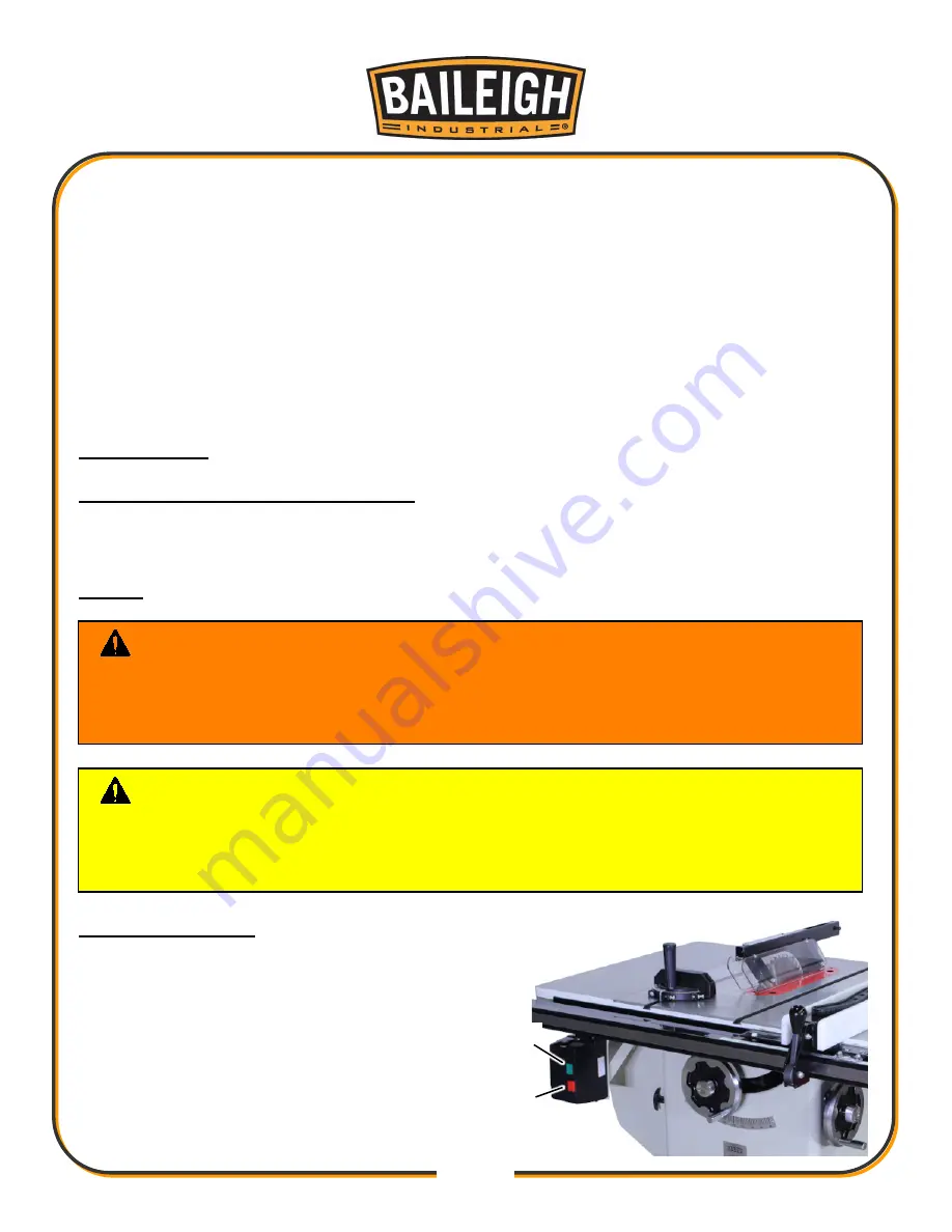
Become familiar with the location and operation 

of the Start and Stop buttons. Practice reaching 

for the buttons, especially the Stop button, with 

power disconnected from the saw. 


  ON Button (Green): (A) Starts the motor. 

  Stop Button (Red): (B) Turns machine OFF. 


WARNING: 

Never operate the saw with any guards or covers removed 

missing or damaged. It could cause severe injury or death. 

Check that saw blade is properly installed and securely tight before operating the 

machine. 

CAUTION: 

Always wear proper eye protection with side shields or a face 

shield, safety footwear, dust mask, and possibly heavy gloves to protect from, chips, 

dust, burrs, and slivers. 

DO NOT stand directly in line with the saw blade when starting. 

Summary of Contents for TS-1040E-30

Page 1: ...C IS PROHIBITED Baileigh Industrial Holdings LLC Inc does not assume and hereby disclaims any liability for any damage or loss caused by an omission or error in this Operator s Manual resulting from a...

Page 2: ...E ASSEMBLY 24 Align the Fence Parallel to the Blade 24 Align the Rip Fence Perpendicular 90 to the Table 25 Level the Fence 25 Adjust Align Rip Fence Pointer 25 Install Change the Blade 26 Riving Knif...

Page 3: ...Parts List A 45 TRUNNION MOTOR PARTS DIAGRAM B 47 Trunnion Motor Parts List B 48 BLADE GUARD PARTS DIAGRAM C 51 Blade Guard Parts List C 52 FENCE 30 50 PARTS DIAGRAM D 53 Fence 30 50 Parts List D 54...

Page 4: ...n notice to Seller of any suspected defect in the Goods prior to the expiration of the warranty period The original end user must also obtain a RGA from Seller prior to returning any Goods to Seller f...

Page 5: ...provided under this Agreement or at law or equity Attorney s Fees In the event legal action is necessary to recover monies due from Buyer or to enforce any provision of this Agreement Buyer shall be l...

Page 6: ...Description of the functional parts of the machine Capacity charts Setup and start up instructions Machine operation Scheduled maintenance Parts lists GENERAL NOTES After receiving your equipment remo...

Page 7: ...zardous situation which if not avoided will result in death or serious injury WARNING Indicates a hazardous situation which if not avoided could result in death or serious injury CAUTION Indicates a h...

Page 8: ...comfortable loud noises DUST HAZARD Wear appropriate dust mask Dust created while using machinery can cause cancer birth defects and long term respiratory damage Be aware of the dust hazards associate...

Page 9: ...or dangerous conditions the machine can be stopped immediately by pressing the E STOP button Twist the emergency stop button clockwise cw to reset Note Resetting the E Stop will not start the machine...

Page 10: ...orse making any modifications or alterations to a Baileigh machine Modifications or alterations to a machine may pose a substantial risk of injury to the operator or others and may do substantial dama...

Page 11: ...o the path of the operator NEVER stand in line with the cutting path of the blade during operation 15 Dress appropriate DO NOT wear loose fitting clothing or jewelry as they can be caught in moving ma...

Page 12: ...ee hole electrical receptacle If an adapter is used to accommodate a two prong receptacle the adapter plug must be attached to a known ground Never remove the third prong 33 Inspect power and control...

Page 13: ...AL SUPPORT Our technical support department can be reached at 920 684 4990 and asking for the support desk for purchased machines Tech Support handles questions on machine setup schematics warranty is...

Page 14: ...y Thickness 0 071 0 086 1 8 2 2mm Required Blade Kerf Thickness 0 102 0 126 2 6 3 2mm Maximum Width of Dado 13 16 8125 20 6mm Maximum Diameter of Dado 8 203mm Blade Tilt Left 0 45 Arbor Size 5 8 625 1...

Page 15: ...rials e g chipboard core board MDF board Solid wood Gypsum plasterboard Cardboard Veneer with a suitable clamping device Dimensionally stable plastics thermoset plastics thermoplastics Sawing these ma...

Page 16: ...age painted surfaces Follow manufacturer s label instructions when using any type of cleaning product After cleaning wipe unpainted metal surfaces with a light coating of quality oil or grease for pro...

Page 17: ...ver The small box consists of the following items 1 Blade Guard Assembly E 1 Riving Knife and Pawl Assembly F 1 Handwheel and Swivel Handle G 1 Lock Knob H 2 Large Hooks J 1 Small Hook K 1 Push Stick...

Page 18: ...er gently to the floor Level the machine so that all the supporting feet are taking the weight of the machine and no rocking is taking place INSTALLATION IMPORTANT Consider the following when looking...

Page 19: ...tes a large amount of weight over a small area Make certain that the floor is capable of supporting the weight of the machine work stock and the operator The floor should also be a level surface If th...

Page 20: ...xtension Wing K Fence Lock Handle C Miter Gauge L Blade Tilt Handwheel w Center Lock D Blade Guard M 4 100mm Dust Port On back E Fence N Fence Storage Supports F Right Extension Wing O Table Tilt Scal...

Page 21: ...nto the Blade Tilt leadscrew shaft Verify that the key is installed into the shaft and engage the slots on the handwheel 6 Install and use the center hand knob D to tighten the handwheels to the shaft...

Page 22: ...n smooth and flat use a wire brush or file if necessary to clean up the edges this step will ensure that the wings mount properly to the main table 6 Loosely attach the wings to the main table with th...

Page 23: ...for the 30 and the 50 table 2 Install the front rail by working from the left end of the table toward the right and loosely install the mounting screws to support and align the front rail using the 1...

Page 24: ...de smoothly when installed 6 On the left end of the table loosen the mounting bolt and remove the nut and washer A 7 Install the switch assembly onto the bolt and install the washer and nut hand tight...

Page 25: ...iron saw table 4 Then tap down the extension table at various points along its edge where it meets the saw table until it is level with the saw table 5 As one part of the edge becomes level with the t...

Page 26: ...egs to the inside corners of the extension table using the eight screws provided Note If you are using a mobile base under your saw you may need to shift the placement of the legs so they rest properl...

Page 27: ...t edge of the fence 1 If the fence is not parallel it can be adjusted by using an Allen wrench to turn one or both of the screws C or D Do this slowly just an eighth to a quarter turn at a time or you...

Page 28: ...e table to fence gap at the outfeed back side and the infeed front side of the table 3 If needed to level the fence adjust the plastic set screws E and F equally thereby raising or lowering the front...

Page 29: ...se to loosen nut Remove arbor nut blade flange B and saw blade 6 Place new blade on arbor Make sure saw blade teeth point down at the front side of saw table Place flange and nut on arbor and securely...

Page 30: ...ease clamp lock handle K in the unlock position 4 The floating clamp block L is spring loaded and will move away O from the fixed block M leaving a gap 5 Insert the bottom of the riving knife N1 N2 al...

Page 31: ...Before operating the table saw verify and follow the Riving Knife adjustment procedure if necessary Riving Knife Adjustment Lateral alignment The saw blade and riving knife must be in line as close a...

Page 32: ...g a 3mm hex wrench make adjustments to any of the four set screws D accessible through openings located in the corners of the floating clamp block E 4 If necessary repeat the above procedure 5 The dis...

Page 33: ...itched on before commencing machining Air current speed is 20m s for vacuum suction dust emission index When air current speed of dust collector device in accordance with EN12779 2004 is not lower tha...

Page 34: ...ndicated on the machine All line connections should make good contact Running on low voltage will damage the motor In the event of a malfunction or breakdown grounding provides a path of least resista...

Page 35: ...0ft 100ft 1 12 16 16 14 13 16 14 12 12 17 20 12 12 10 21 30 10 10 No WIRE GAUGE An undersized cord decreases line voltage causing loss of power and overheating All cords should use a ground wire and p...

Page 36: ...3 Tighten the lock knob D Blade tilt adjustment 1 Loosen the lock knob E on the side handwheel B 2 Turn the handwheel B counterclockwise to adjust the saw blade down to 45 left tilt Turn clockwise to...

Page 37: ...blade 1 Disconnect the saw from the power source 2 Raise the blade guard up a way from the blade 3 Choose a tooth on the back output side of the blade and position the tooth slightly above the table i...

Page 38: ...wn 5 Place a combination square on the table against the blade Make sure square is not touching a blade tooth 6 If the blade is not 45 a Open the motor cover b Loosen the jam nut and turn adjusting st...

Page 39: ...commend you get the feel of operations using scrap lumber to check settings Read entire instructions before you start to cut workpiece Always pay attention to safety precautions to avoid personal inju...

Page 40: ...e miter gauge may be used in either table slot however most operators prefer the left groove for average work When bevel cutting blade tilted use the table groove that does not cause interference of y...

Page 41: ...ck holding it down and against the fence Never stand in direct line of the saw blade cut when ripping Hold the work stock with both hands and push it along the fence and into the saw blade The work st...

Page 42: ...f groove A 1 4 6 3mm groove is cut by using the two outside blades The teeth of the blades should be positioned so that the raker on one saw is beside the cutting teeth on the other saw The dado heads...

Page 43: ...r housing with compressed air Wipe down the fence rails with a dry silicon lubricant Clean and oil the tables so that the material will slide easily Clean any rust spots that may develop on the bed wi...

Page 44: ...d a stiff wire brush or steel wool Make sure the internal workings are dry before using the saw again so that wood dust will not accumulate If any essential lubrication is removed during cleaning re l...

Page 45: ...le Turn blade around Remove blade and clean Change blade to correct type Clean table Blade does not come up to speed Extension cord too light or long Low shop voltage Motor not wired for correct volta...

Page 46: ...dull Replace blade Push material all the way past blade before releasing work Replace or sharpen kick back plates Blade does not raise or tilt freely Sawdust and debris in raising and tilting mechani...

Page 47: ...44 44 TABLE CABINET PARTS DIAGRAM A...

Page 48: ...ert Optional Accessory 14 TS1040EV3 A14 Table 1 15 TS1040EV3 A15 Extension Wing 2 18 TS1040EV3 A18 Hex Cap Screw 7 16 14x1 1 2 6 19 TS1040EV3 A19 Lock Washer 7 16 6 20 TS1040EV3 A20 Flat Washer 7 16 1...

Page 49: ...0EV3 A45 Handle 1 47 TS1040EV3 A47 Socket Head Cap Screw 7 16 14x3 4 4 48 TS1040EV3 A48 Flat Washer 3 16 2 49 TS1040EV3 A49 Lower Panel 1 50 TS1040EV3 A50 Dust Hose Adapter 1 51 TS1040EV3 A51 Switch B...

Page 50: ...47 47 TRUNNION MOTOR PARTS DIAGRAM B...

Page 51: ...Washer 3 8 10 114 TS1040EV3 B114 Arbor Bracket 1 115 TS1040EV3 B115 Spanner Nut 1 116 TS1040EV3 B116 Nut 5 8 1 117 TS1040EV3 B117 Spring Pin M6x50 1 118 TS1040EV3 B118 Key 1 4x1 4x2 5 16 1 119 TS1040...

Page 52: ...2 TS1040EV3 B142 Socket Set Screw 5 16 18x1 4 4 143 TS1040EV3 B143 Collar 2 144 TS1040EV3 B144 Shaft 1 145 TS1040EV3 B145 Spring Pin M5x30 2 146 TS1040EV3 B146 Worm Left thread 2 146 1 TS1040EV3 B146...

Page 53: ...24x3 8 3 178 TS1040EV3 B178 Special Screw 1 179 TS1040EV3 B179 Arbor Lock Insert Assembly 179 1through 179 5 179 1 TS1040EV3 B179 1 Arbor Lock Insert 8 1 179 2 TS1040EV3 B179 2 Spring 1 179 3 TS1040EV...

Page 54: ...93 TS1040EV3 B193 Clamping Block 1 194 TS1040EV3 B194 Flat Head Socket Screw M6X20 2 195 TS1040EV3 B195 Locking Handle 1 196 TS1040EV3 B196 Nylon Insert Lock Nut M8 1 197 TS1040EV3 B197 Spring Shim Ri...

Page 55: ...6 x 16 8 8 TS1040EV3 C8 Front Shield 1 9 TS1040EV3 C9 Bushing 1 10 TS1040EV3 C10 Top Sight Shield 1 11 TS1040EV3 C11 Nylon Insert Lock Nut M6 8 12 TS1040EV3 C12 Pan Head Screw 8 32x1 4 2 13 TS1040EV3...

Page 56: ...53 53 FENCE 30 50 PARTS DIAGRAM D...

Page 57: ...w 10 32 x 3 8 2 11 TS1040EV3 D11 Flat Washer 1 4 2 12 TS1040EV3 D12 Flat Head Machine Screw 10 32 x 3 8 2 13 TS1040EV3 D13 Cursor 1 14 TS1040EV3 D14 Cursor Bracket 1 15 TS1040EV3 D15 Lock Nut 1 4 20 1...

Page 58: ...55 55 FENCE RAIL 30 50 PARTS DIAGRAM E...

Page 59: ...E3 Flat Washer 1 4 24 4 TS1040EV3 E4 Lock Washer 1 4 19 5 TS1040EV3 E5 Hex Nut 1 4 20 12 6 TS1040EV3 E6 Hex Cap Screw 1 4 20 x 3 4 7 7 TS1040EV3 E750 Scale 50 1 TS1040EV3 E730 Scale 30 1 8 TS1040EV3...

Page 60: ...No Description Qty 1 TS1040EV3 F1 Leg 2 2 TS1040EV3 F2 Hex Nut 3 8 16 2 3 TS1040EV3 F3 Adjusting foot 2 4 TS1040EV3 F4 Machine Screw M5 16 8 BAILEIGH INDUSTRIAL HOLDINGS LLC 1625 DUFEK DRIVE MANITOWO...

Reviews: