background image


THANK YOU & WARRANTY 

Thank you for your purchase of a machine from Baileigh Industrial Holdings LLC. We hope that 
you find it productive and useful to you for a long time to come. 


Inspection  &  Acceptance.

  Buyer  shall  inspect  all  Goods  within  ten  (10)  days  after 

receipt  thereof.  Buyer’s 

payment shall constitute final acceptance of the Goods and shall act as a waiver of the Buyer’s rights to inspect or 
reject  the  goods  unless  otherwise  agreed.  If  Buyer  rejects  any  merchandise,  Buyer  must  first  obtain  a  Returned 
Goo

ds Authorization (“RGA”) number before returning any goods to Seller. Goods returned without a RGA will be 

refused.  Seller  will  not  be  responsible  for  any  freight  costs,  damages  to  goods,  or  any  other  costs  or  liabilities 
pertaining to goods returned without an RGA. Seller shall have the right to substitute a conforming tender. Buyer 
will be responsible for all freight costs to and from Buyer and repackaging costs, if any, if Buyer refuses to accept 
shipment.  If  Goods  are  returned  in  unsalable  condition,  Buyer  shall  be  responsible  for  full  value  of  the  Goods. 
Buyer may not return any special-order Goods. Any Goods returned hereunder shall be subject to a restocking fee 
equal to 30% of the invoice price. 
 

Specifications.

 Seller may, at its option, make changes in the designs, specifications or components of the Goods 

to improve the safety of such Goods, or if in Seller’s judgment, such changes will be beneficial to their operation or 
use. Buyer may not make any changes in the specifications for the Goods unless Seller approves of such changes 
in writing, in which event Seller may impose additional charges to implement such changes. 
 

Limited  Warranty.

  Seller  warrants  to  the  original  end-user  that  the  Goods  manufactured  or  provided  by  Seller 

under this Agreement shall be free of defects in material or workmanship for a period of twelve (12) months from 
the  date  of  purchase,  provided  that  the  Goods  are  installed,  used,  and  maintained  in  accordance  with  any 
instruction  manual  or  technical  guidelines  provided  by  the  Seller  or  supplied  with  the  Goods,  if  applicable.  The 
original end-user must give written notice to Seller of any suspected defect in the Goods prior to the expiration of 
the  warranty  period.  The  original  end-user  must  also  obtain  a  RGA  from  Seller  prior  to  returning  any  Goods  to 
Seller for warranty service under this paragraph. Seller will not accept any responsibility for Goods returned without 
a RGA. The original end-user shall be responsible for all costs and expenses associated with returning the Goods 
to Seller for warranty service. In the event of a defect, Seller, at its sole option, shall repair or replace the defective 
Goods  or  refund  to  the  original  end-user  the  purchase  price  for  such  defective Goods.  Goods  are  not  eligible  for 
replacement  or  return  after  a  period  of  1

0  days  from  date  of  receipt.  The  foregoing  warranty  is  Seller’s  sole 

obligation, and the original end-

user’s exclusive remedy, with regard to any defective Goods. This limited warranty 

does not apply to: (a) die sets, tooling, and saw blades; (b) periodic or routine maintenance and setup, (c) repair or 
replacement of the Goods due to normal wear and tear, (d) defects or damage to the Goods resulting from misuse, 
abuse,  neglect,  or  accidents,  (f)  defects  or  damage  to  the  Goods  resulting  from  improper  or  unauthorized 
alterations,  modifications,  or  changes;  and  (f)  any  Goods  that  has  not  been  installed  and/or  maintained  in 
accordance with the instruction manual or technical guidelines provided by Seller. 
 

EXCLUSION OF OTHER WARRANTIES.

 THE FOREGOING LIMITED WARRANTY IS IN LIEU OF ALL OTHER 

WARRANTIES,  EXPRESS  OR  IMPLIED.  ANY  AND  ALL  OTHER  EXPRESS,  STATUTORY  OR  IMPLIED 
WARRANTIES,  INCLUDING  BUT  NOT  LIMITED  TO,  ANY  WARRANTY  OF  MERCHANTABILITY  OR  FITNESS 
FOR  ANY  PARTICULAR  PURPOSE  ARE  EXPRESSLY  DISCLAIMED.  NO  WARRANTY  IS  MADE  WHICH 
EXTENDS BEYOND THAT WHICH IS EXPRESSLY CONTAINED HEREIN. 
 

Limitation  of  Liability.

  IN  NO  EVENT  SHALL  SELLER  BE  LIABLE  TO  BUYER  OR  ANY  OTHER  PARTY  FOR 

ANY  INCIDENTIAL,  CONSEQUENTIAL  OR  SPECIAL  DAMAGES  (INCLUDING,  WITHOUT  LIMITATION,  LOST 
PROFITS OR DOWN TIME) ARISING FROM OR IN MANNER CONNECTED WITH THE GOODS, ANY BREACH 
BY  SELLER  OR  ITS  AGENTS  OF  THIS  AGREEMENT,  OR  ANY  OTHER  CAUSE  WHATSOEVER,  WHETHER 

BASED ON CONTRACT, TORT OR ANY OTHER THEORY OF LIABILITY. BUYER’S REMEDY WITH RESPECT 
TO  ANY  CLAIM  ARISING  UNDER  THIS  AGREEMENT  IS  STRICTLY  LIMITED  TO  NO  MORE  THAN  THE 
AMOUNT PAID BY THE BUYER FOR THE GOODS. 


Summary of Contents for IP-1306

Page 1: ...ndustrial Holdings LLC does not assume and hereby disclaims any liability for any damage or loss caused by an omission or error in this Operator s Manual resulting from accident negligence or other oc...

Page 2: ...cord connection 18 ADJUSTMENTS 19 Levelling Extension Tables 19 Raising and Lowering Head Assembly 20 Adjusting Replacing Knives 20 Thickness Scale Adjustment 22 Cutting Depth Gauge 22 Repeat Cut Pre...

Page 3: ...Feed Roller Inspection 34 PLANER PARTS DIAGRAM A 35 Planer Parts List A 36 MOTOR PARTS DIAGRAM B 40 Motor Parts List 41 TROUBLESHOOTING 42...

Page 4: ...n notice to Seller of any suspected defect in the Goods prior to the expiration of the warranty period The original end user must also obtain a RGA from Seller prior to returning any Goods to Seller f...

Page 5: ...es provided under this Agreement or at law or equity Attorney s Fees In the event legal action is necessary to recover monies due from Buyer or to enforce any provision of this Agreement Buyer shall b...

Page 6: ...ption of the functional parts of the machine Capacity charts Setup and start up instructions Machine operation Scheduled maintenance Parts lists GENERAL NOTES After receiving your equipment remove the...

Page 7: ...zardous situation which if not avoided will result in death or serious injury WARNING Indicates a hazardous situation which if not avoided could result in death or serious injury CAUTION Indicates a h...

Page 8: ...Dust created while using machinery can cause cancer birth defects and long term respiratory damage Be aware of the dust hazards associated with all types of materials DUST PARTICLES AND IGNITION SOURC...

Page 9: ...out guards in place Power Switch with Lock Out In the event of incorrect operation or dangerous conditions the machine can be stopped immediately by pressing the Power Switch paddle downward Remove th...

Page 10: ...modifications or alterations to a Baileigh machine Modifications or alterations to a machine may pose a substantial risk of injury to the operator or others and may do substantial damage to the machi...

Page 11: ...y check any part that appears damaged Check for alignment and binding of moving parts that may affect proper machine operation 14 Keep work area clean Cluttered areas invite injuries 15 Observe work a...

Page 12: ...jurious to your health Always operate machinery in well ventilated areas and provide for proper dust removal Use a wood dust collection system whenever possible 35 Respiratory Protection Wear an appro...

Page 13: ...m Head Movement Per Handle Revolution 1 16 0625 1 5mm Feed Speed F min 26FPM 7 9MPM Thickness Gauge Stops 1 8 1 4 1 2 3 4 1 1 1 4 1 1 2 1 3 4In Number of Cutterhead Rows 6 Cutter Inserts Qty 26 2 side...

Page 14: ...des For specific application needs or future machine purchases contact the Sales Department at sales baileigh com Phone 920 684 4990 or Fax 920 684 3944 Note The photos and illustrations used in this...

Page 15: ...age painted surfaces Follow manufacturer s label instructions when using any type of cleaning product After cleaning wipe unpainted metal surfaces with a light coating of quality oil or grease for pro...

Page 16: ...hrough the machine Space needed for auxiliary stands work tables or other machinery Clearance from walls and other obstacles Maintain an adequate working area around the machine for safety Have the wo...

Page 17: ...tain that the floor is capable of supporting the weight of the machine work stock and the operator The floor should also be a level surface If the unit wobbles or rocks once in place be sure to elimin...

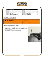
Page 18: ...ASSEMBLY AND SET UP Attaching Depth Adjustment Handle Attach the raise lower adjustment handle to the shaft located on top of the planer and fasten in place with 1 Hex Socket Head screw Tighten screw...

Page 19: ...2 inch dust hose use the 4 inch to 2 1 2 inch adaptor Important Dryer vent hose is not acceptable for the collection of wood dust and chips Important If a dust collection system is not used do not ins...

Page 20: ...ndicated on the machine All line connections should make good contact Running on low voltage will damage the motor In the event of a malfunction or breakdown grounding provides a path of least resista...

Page 21: ...50ft 100ft 1 12 16 16 14 13 16 14 12 12 17 20 12 12 10 21 30 10 10 No WIRE GAUGE An undersized cord decreases line voltage causing loss of power and overheating All cords should use a ground wire and...

Page 22: ...o make sure that the infeed table is level with the planer table If an adjustment is necessary raise table loosen lock nuts D and adjust Hex Head Screws E on each side of the table until the infeed ta...

Page 23: ...ckness Use this feature when thickness planing multiple workpieces to ensure a uniform thickness of all workpieces Do not attempt to lower the cutterhead assembly below the preset level as damage will...

Page 24: ...ly clean all dust and dirt off the cutter tip and the cutterhead seat 7 Replace or rotate the cutter insert so a fresh sharp edge is facing outward If available use pitch remover to be sure all wood r...

Page 25: ...ting depth of cut The bottom of the gauge ball has been set even with the cutterhead knives 1 With the machine OFF insert workpiece far enough about 2 inches that it lies beneath the gauge ball A Veri...

Page 26: ...ever to the desired finished thickness Use this feature when thickness planning multiple workpieces to ensure a uniform thickness of all workpieces Note When lowering the head assembly ensure the REPE...

Page 27: ...y pull out the yellow key A located on the face of the switch Circuit Breaker Reset The planer is equipped with a motor protective circuit breaker The breaker will shut the planer off automatically wh...

Page 28: ...length Note For longer pieces be sure to use additional supports or stands 6 Push slightly on the board to start feed and allow the feed rollers to pull the board through the planer Once the feed rol...

Page 29: ...ny variables determine suitable depth of cut such as wood width density grain structure dampness etc For best results use shallow cuts and multiple passes Excessive depth of cut will place undue strai...

Page 30: ...ue up glued together stock follow these suggestions As you glue the stock scrub off all the glue on the surface with a wet rag This prevents glue beads from forming on the wood surface Allow the glue...

Page 31: ...feed rollers will press it flat for the pass but the wood will spring back into cupped form when it has cleared the rollers For best results one side of the material should be run through a jointer to...

Page 32: ...e grain direction will be consistent on both pieces Otherwise use personal judgment as to which direction is more favorable and safer for feeding Edge grain may be planed if the stock is wide enough t...

Page 33: ...Feed the board into the planer so the knives cut with the grain Measure the rough lumber at several locations to find the thickest part As wood dries its dimensions vary including its thickness Set th...

Page 34: ...d air may damage insulation The operator should always wear a respirator and eye protection when using compressed air Do not allow chips and dust to accumulate under the machine Keep area clean and in...

Page 35: ...ace all covers panels and guards that you removed once lubrication is complete Brush Replacement Brush life will vary depending on the load placed on the motor The brushes should be inspected every 20...

Page 36: ...ased from the tops of the columns 4 Carefully maneuver the right side cover from beneath the top plate Then lift the side cover out of the groove in the planer base 5 Remove two screws B with Phillips...

Page 37: ...d shaft through the access hole 3 Insert 4mm hex wrench through hole and into recess Use this wrench to rotate cutterhead and rollers during the inspection process 4 Inspect both rollers for sawdust a...

Page 38: ...35 35 PLANER PARTS DIAGRAM A...

Page 39: ...L 2 13 IP1306 A13 Idler 2 14 IP1306 A14 Idler Shaft 2 15 IP1306 A15 Spindle 3 16 IP1306 A16 Height Adjust Spindle 1 17 IP1306 A17 Hex Socket Head Screw M5xP0 8x20L 1 18 IP1306 A18 Hand Knob Assembly 1...

Page 40: ...Helical Cutterhead 1 IP1306 TCI Tungsten Carbide Insert Set 10pcs set req 3 sets 26 IP1306 TS Torx Screw M5xP0 8x9 6L 26 72 IP1306 A72 Hex Nut M10 X14XP1 5 1 74 IP1306 A74 Hex Nut M5XP0 8 1 75 IP1306...

Page 41: ...1 131 IP1306 A131 Step Block Pin 1 132 IP1306 A132 Hex Nut M6XP1 0 1 133 IP1306 A133 Spring 7 62X 15 75X 0 7 1 134 IP1306 A134 Steel Ball 10MM 1 135 IP1306 A135 Pivot Rod 1 136 IP1306 A136 Adjust Scr...

Page 42: ...t No Description Qty 191 IP1306 A191 Logo Label Baileigh 1 195 IP1306 A195 Specification Label 1 198 IP1306 A198 Side Label 1 203 IP1306 A203 Safety Warning Label 1 600 IP1306 A600 Motor Switch Assemb...

Page 43: ...40 40 MOTOR PARTS DIAGRAM B...

Page 44: ...IP1306 B175 Pan Hd Screw W Washer M5 8L 1 176 IP1306 B176 Lead Wire 300mm 1 177 IP1306 B177 Lockwasher External M5 1 178 IP1306 B178 Screw Sems L Washer M4 2 20L 4 179 IP1306 B179 Heat Shrinkable Tubi...

Page 45: ...erheats resulting in tripped breaker Motor overloaded Reduce load on motor try less depth of cut or slower feed rate Make sure knife inserts are sharp Low voltage Correct the low voltage conditions In...

Page 46: ...Dull knives or debris building up on cutterhead Clean cutterhead rotate or replace knife inserts clean out dust hood if being used Drive belt slipping or damaged Replace belt Uneven depth of cut side...

Page 47: ...44 44 NOTES...

Page 48: ...45 45 BAILEIGH INDUSTRIAL HOLDINGS LLC 1625 DUFEK DRIVE MANITOWOC WI 54220 PHONE 920 684 4990 FAX 920 684 3944 www baileigh com...

Reviews: