20
20
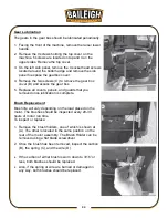
Raising and Lowering Head Assembly
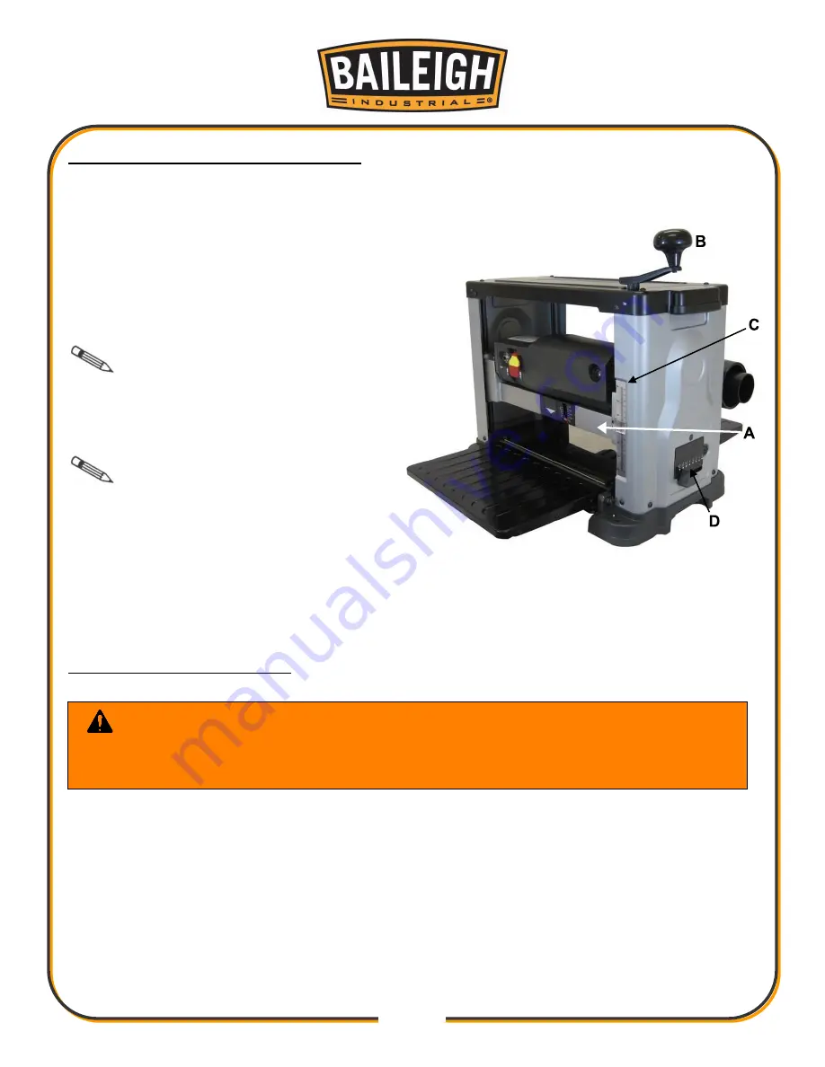
The head assembly consists of the cutterhead, knives, feed rollers, cutterhead guard, and the
motor. Raising and lowering of the head assembly controls the depth of cut on the planer.
To adjust:
•
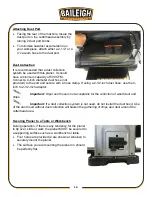
To raise the head assembly (A), turn the
adjusting handle (B) clockwise.
•
To lower the head assembly, turn the
adjusting handle counterclockwise.
Note: One revolution of the
handle will move the cutterhead up or down
approximately 1/16", .0625” (1.5mm). You
can confirm this by referencing the scale (C)
on the front right side of the planer.
Note: The Repeat Cut
Thickness Indicator (D), located on the
bottom right side of the planer, provides a
simple way to preset the finished thickness of
a workpiece. Slide the indicator to the
desired finished thickness. Use this feature when thickness planing multiple workpieces to
ensure a uniform thickness of all workpieces. Do not attempt to lower the cutterhead assembly
below the preset level as damage will occur.
Adjusting / Replacing Knives
This 13" cutterhead is equipped with 26 indexable cutter inserts. Each cutter insert can be
rotated to reveal one of its two cutting edges. Therefore, if one cutting edge becomes dull or
damaged, simply rotate it 90° to reveal a fresh cutting edge.
In addition, each cutter insert has a reference dot on one corner. As the cutter insert is rotated,
the reference dot location can be used as an indicator of which edges are used and which are
new. When the reference dot revolves back around to its starting position, the cutter should be
replaced.
WARNING:
To prevent serious personal injury NEVER rotate the
cutterhead by hand without protection. Cutter insert are razor sharp! Always wear
heavy leather gloves when handling the cutterhead.
Summary of Contents for IP-1306
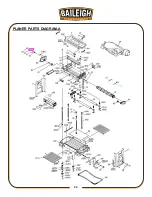
Page 38: ...35 35 PLANER PARTS DIAGRAM A...
Page 43: ...40 40 MOTOR PARTS DIAGRAM B...
Page 47: ...44 44 NOTES...

