17
17
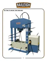
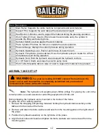
Item Description
A
Main Frame; Supports the entire machine components and work material.
B
Support Pins; Supports the work table at the desired work height.
C
Heal Blocks / V-Blocks; used to support the material during the pressing operation.
D
Work Table Lift Chain; Used to lift and lower the work table using the cylinder to
provide the lifting and lowering force.
E
Serrated Saddle; presses against the work material.
F
Press Cylinder; Provides the force to complete the press operation.
G
Pressure Gauge; displays the current pressure during operation.
H
Hydraulic Operating Lever; Push or pull to raise or lower the ram.
I
Hydraulic Pump Motor (inside cabinet); Runs the hydraulic pump to create the oil flow
and pressure used during operation.
J
Hydraulic Tank; Hold the hydraulic oil and support the hydraulic controls.
K
On / Off Switch. Starts and stops the electric pump motor.
L
Work Table; Moveable table to raise or lower to support the material to be pressed.
ASSEMBLY AND SET UP
Note:
The hydraulic unit weights about 200lbs (95kg). For placing the unit in the
correct position, use and assistant or safe lifting equipment to lift the unit.
During shipping, the hydraulic unit is mounted in the inside of the frame.
To place the unit in working position:
1. Remove the strapping and packing materials holding the hydraulic tank assembly on the
table and to the inside of the frame.
2. Remove and retain the bolts, washers and nuts from the mounting plate on the right side of
the press.
3. Position the hydraulic assembly on the right side of the press.
4. Align the bolt holes and install and tighten the bolts, washers and nuts removed from the
mounting plate.
WARNING:
For your own safety, DO NOT connect the machine to the
power source until the machine is completely assembled and you read and
understand the entire instruction manual.
Summary of Contents for HSP-176M-HD
Page 3: ...ELECTRICAL SCHEMATIC 38 Electrical Parts List 38 TROUBLESHOOTING 39 ...
Page 19: ...16 16 GETTING TO KNOW YOUR MACHINE A I G H L J B F K C E D ...
Page 30: ...27 27 Using the Machine Incorrect Correct ...
Page 31: ...28 28 Incorrect Correct ...
Page 37: ...34 34 RAM PARTS DIAGRAM ...
Page 39: ...36 36 HYDRAULIC PUMP PARTS DIAGRAM ...
Page 43: ...40 40 NOTES ...


