26
26
Table Adjustment
Lifting the table is performed using the lifting chain attached from the ram to the table.
1. If lifting the table; start with the piston
extended to full stroke. If lowering the table;
start with the piston extended about 1”
(25mm).
2. Install the eye bolt into the end of the ram
and hand tighten.
3. Feed the chain through the eye bolt and
around the two center cross bars. Remove as
much slack form the chains as possible and
link the hook onto the chain.
4. Raise the piston enough to lift the table to
remove the table support pins.
5. Remove the retaining pins from the back of
the support pins.
6. If lowering the table, install the support pins
the desired holes. If raising the table, raise
the table high enough to expose the holes
below the table and then install the support
pins.
7. When the support pins are in the desired
holes, install the retaining pins on the back of
the support pins.
Note:
The table always needs to be higher than the hole you want to place the
support pin. It may be necessary to reach the desired table position in more than one step.
8. The support pin is installed correctly when the collar is tight to the table and the table slot
rests fully on the pin.
9. Lower the table until it rests on both support pins.
10. Remove the lifting chain out of the working area.
IMPORTANT:
NEVER lift or lower the table with tooling or material or
pressure from the ram on the table. This will damage the machine voiding the
warranty.
Summary of Contents for HSP-176M-HD
Page 3: ...ELECTRICAL SCHEMATIC 38 Electrical Parts List 38 TROUBLESHOOTING 39 ...
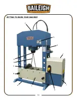
Page 19: ...16 16 GETTING TO KNOW YOUR MACHINE A I G H L J B F K C E D ...
Page 30: ...27 27 Using the Machine Incorrect Correct ...
Page 31: ...28 28 Incorrect Correct ...
Page 37: ...34 34 RAM PARTS DIAGRAM ...
Page 39: ...36 36 HYDRAULIC PUMP PARTS DIAGRAM ...
Page 43: ...40 40 NOTES ...


