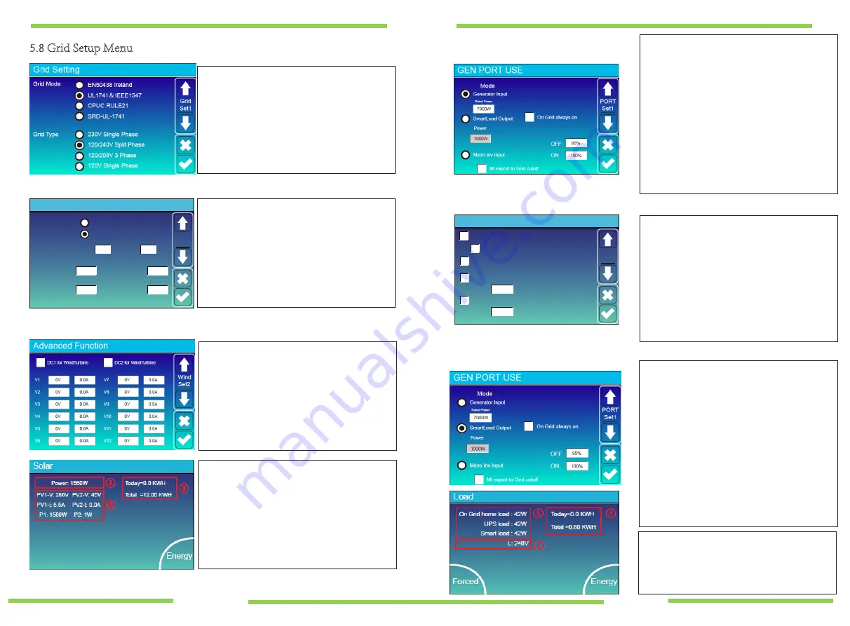
Badger Power Electronics BPE-HI-3.6K User Manual Download Page 16

5.8 Grid Setup Menu

Grid Setting

Grid Mode

Grid Type

General Standard

UL1741

IEEE1547

CPUC RULE21
SRD-UL-1741

120/240V Split Phase
120/208V 3 Phase
120V Single Phase

220V Single Phase

Grid

Set1

PF

Grid Frequency

Reconnection Time

Grid Vol High

Grid Vol Low

Grid HZ High

Grid HZ Low

Grid Setting

50HZ
60HZ

1.000

60S

265.0V

185.0V

60.5Hz

59.3Hz

Grid

Set2

Mode

OFF

ON

Generator Input

SmartLoad Output

Micro Inv Input

Gen connect to Grid input

On Grid always on

Ml export to Grid cutoff

GEN PORT USE

60Min

100%

95%

Power

Open Delay

1000W

PORT

Set1

Clear Arc_Fault

Solar Arc Fault ON

System selfcheck

Gen peak-shaving
Power

7000W

Grid peak-shaving
Power

4000W

Advanced Function

Func

Set1

V

V2

V3

V4

V5

V6

V7

V8

V9

V10

V11

V12

0V

0.0A

0.0A

0.0A

0.0A

0.0A

0.0A

0V

0V

0V

0V

0V

0V

0.0A

0.0A

0.0A

0.0A

0.0A

0.0A

DC1 for WindTurbine

Wind

Set2

Please select the correct Grid Mode in your local area.


Please select the correct Grid Type in your local area, 

otherwise the inverter will not work or be damaged.

The parameters in this screen will automatically update 
 dependent on which Grid Mode you have selected.

Solar Arc Fault ON

---This is only for the US.

System self-check

  ---Disable.

Gen Peak-shaving

---Enable when the power of the 

generator exceeds its rated value, the inverter will 

provide the redundant power to ensure that the 

generator doesn't overload.

Grid Peak-shaving

---Enable  when the power of the 

grid exceeds the set value, the inverter will provide 

the redundant part to ensure that the grid power 

does not exceed the set value.

The Generator port can only be used for one input/output. 

It can be used for a generator input OR smart load output 

OR micro inverter input.

Generator Input 

- If connected to a generator.

Gen connected to Grid input

 - In off-grid applications the 

generator can also be connected to the Grid input port.

SmartLoad Output 

- See 5.12 below

Micro Inv Input 

- Use the Gen Port as an AC coupled input, 

this will also work with "Grid-Tied" Inverters.

Off

 - Battery SOC to disable the AC coupled input (95-100%)

ON 

- Battery SOC to enable AC coupled input (50-60%)

AC Coupled priority -  LOAD - BATTERY - EXPORT unless MI 

export to grid is deselected then the AC coupled input will 

turn  off  once  the  battery  SOC  reaches  the  preset  "OFF" 

value.

- 25 -

- 26 -

5.9 Wind Turbine Input

5.10 Generator  Port Use Setup Menu

5.11 Advanced Function Setup Menu

5.12 Smart Load


(Gen Load)

nction Setup Menu

By pressing the Forced icon on the Load display 

screen for 6 seconds this will 

force open

 the Smart 

Load 

output 

and manually override the user 

programmable settings. 

To disable Forced Smart Load please repeat the 

above step.

In Advanced settings you can insert the 12 

power curve settings for wind.

All points must be higher then the previous.

Select if you are using string 1 or 2.

Always use a BPE wind controller to connect 

the wind turbine.

You can have any combination of inputs.

Wind / Wind


Solar / Wind


Solar / Solar


This mode utilises the Gen input connection as a Smart 

Load output which only receives power when the 

battery SOC and PV/Wind generation is above a user 

programmable threshold.
The Gen input port in the user area of the system 

becomes an output to high power loads such as a water 

heater, irrigation pump, ac unit or any other device.

On Grid always on

: When connected to the grid the 

smart load will be always on.

Power 

- Minimum PV/Wind generation (W) to enable 

smart load. 

OFF 

- Battery SOC to disable Smart Load output.

ON 


Battery SOC to enable Smart Load output.

Summary of Contents for BPE-HI-3.6K

Page 1: ...HYBRID INVERTER SOLAR STORAGE WIND BACK UP GENERATOR USER MANUAL BPE HI 3 6K BPE HI 5K...

Page 2: ...10 Single phase parallel connection diagram 3 11Three phase Parallel Inverter 4 OPERATION 4 1 Power ON OFF 4 2 Operation and Display Panel 5 LCD Display Icons 5 1 Main Screen 5 2 Solar Power Curve 5 3...

Page 3: ...gramme the time of use settings selecting Time Of Use will allow the battery to be discharged to the load until a user set SOC is reached during the pre set 6 time periods You can also select whether...

Page 4: ...parts and even cause an explosion Please follow the installation procedure when you want to disconnect AC or DC terminals Please refer to Installation section of this manual for details Grounding ins...

Page 5: ...erformance Time of use function Smart Load Function Parallel function On Grid Off Grid 2 3 Basic System Architecture The following illustration shows basic application of this inverter It also include...

Page 6: ...stall this inverter at eye level in order to allow the LCD display to be read at all times Chart 3 1 Parts List 3 2 Mounting instructions Installation Precaution This Hybrid inverter is designed for o...

Page 7: ...follow the below steps to implement battery connection 1 Please choose a suitable battery cable with the correct connector which can fit into the battery terminals 2 Use a suitable screwdriver to uns...

Page 8: ...ut connection be sure to open the DC protector or disconnecter first 2 Remove 10mm of the insulation sleeve unscrew the bolts insert the AC input cables according to polarities indicated on the termin...

Page 9: ...ant for system safety and efficient operation to use the appropriate cable for PV module connection To reduce risk of injury please use the recommended cable size as below Be sure that the AC power so...

Page 10: ...tive conductor fails 3 8 WIFI Connection For the configuration of the Wi Fi Plug please refer to illustrations of the Wi Fi Plug at the end of this user manual Battery Solar Breaker CAN Breaker Breake...

Page 11: ...er Inverter No 3 slave Ground Inverter No 2 slave Inverter No 1 master Battery pack L wire CAN N wire PE wire Battery pack Grid CAN L1 L2 L3 N PE Load GEN Grid Load GEN Grid Load GEN Grid Inverter No...

Page 12: ...rt from grid Battery power negative means charge positive means discharge 4 OPERATION 4 1 Power ON OFF Once the unit has been correctly installed and the batteries are connected simply press the On Of...

Page 13: ...d When GEN PORT is utilised as Smart load output Power 0W Stand by 0 0Hz Energy CT1 0W L1 0V L2 0V Import Today 0 0KWH Total 8 60 KWH Today 2 2KWH Total 11 60 KWH Export LD1 0W CT2 0W LD2 0W Grid Grid...

Page 14: ...0A 30 6C 52 0 26 0Ah 0 0V 0 0A 0 0 0 50 33V 19 10A 31 0C 51 0 25 5Ah 53 2V 25 0A 0 0 0 50 30V 16 90A 30 2C 12 0 6 0Ah 53 2V 25 0A 0 0 0 4 5 0 00V 0 00A 0 0C 0 0 0 0Ah 0 0V 0 0A 0 0 0 0 00V 0 00A 0 0C...

Page 15: ...57 6V Equalization V 58 8V Equalization Days Shutdown Low Batt Restart TEMPCO mV C Cell Batt Resistance 90 days Equalization Hours 2 0 hours 25mOhms Battery Settings Set3 Batt Time Of Use Time System...

Page 16: ...R smart load output OR micro inverter input Generator Input If connected to a generator Gen connected to Grid input In off grid applications the generator can also be connected to the Grid input port...

Page 17: ...0 0 0 0 00V 0 00A 0 0C 0 0 0 0Ah 0 0V 0 0A 0 0 0 0 00V 0 00A 0 0C 0 0 0 0Ah 0 0V 0 0A 0 0 0 0 00V 0 00A 0 0C 0 0 0 0Ah 0 0V 0 0A 0 0 0 0 00V 0 00A 0 0C 0 0 0 0Ah 0 0V 0 0A 0 0 0 0 00V 0 00A 0 0C 0 0...

Page 18: ...Information Error Code Diagnosis and Solution F13 F18 F20 F23 F24 F26 F30 F35 F41 F42 Inverter working mode change please wait one minute Working_Mode_change AC side over current fault Please check th...

Page 19: ...or operation Damage caused by insufficient ventilation of equipment Damage caused by failure to comply with applicable safety standards or regulations Damage caused by natural disasters or force majeu...

Page 20: ...harmonic distortion Single Phase THD 3 Linear load 1 5 3 Stages equalization Optional Self adaption to BMS 4680W 6500W 11A 11A 2 1 1 370V 100V 500V 125 425V 125V 3600W 5000W 3960W 5500W 21 7A 15 7A Ma...

Page 21: ...1 SOLARMAN Business App Configuration FOR INSTALLERS...

Page 22: ...oid SOLARMAN Smart 2 Download the SOLARMAN Business app As the installer or business owner download the SOLARMAN Business app onto a smartphone or tablet Create an account if you do not already have o...

Page 23: ...device and selecting the network beginning AP from the list Once you have selected the AP network you will be asked for the network password The password can be found on the dongle or on the box sign...

Page 24: ...ype the following credentials Username admin Password admin You will then be taken to an index page titled Inverter information From this page select Wizard in the menu Select your preferred network L...

Page 25: ...5 Select the next button and input your local network password On page 2 3 select Next Once in page four finalise the network configuration by selecting OK...

Page 26: ...e relevant detail regarding the customer s system For the purpose of this manual we only enter Plant Name and Installed Capacity but you should enter all the information you can If your system include...

Page 27: ...7...

Page 28: ...n move forward to selecting the Authorise User icon 9 Authorise Customer as User Select Authorise User and click the add user icon in the top right hand corner of the screen A pop up menu should then...

Page 29: ...has logged in to SOLARMAN Smart and the plant is visible they can press the three dots on the top right of the home page select Plant Info and they can upload a picture of their PV array to have as th...

Reviews: